
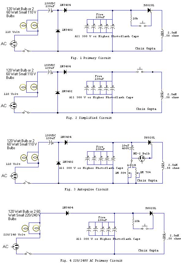
Build a Low cost & simple Magnetic Pulser
Finally, at long last here is an extensive update (of the 2003-08-19 original) that many have been requesting. Some additions are:
- Basic 220/240 Volt AC Circuit.
- A Simple auto pulsing Circuit.
- 12 V DC Operation
- High Power vs low power - discussion
- Polarity of Coil.
- Various other embellishments and updates - that should address many questions in the comments
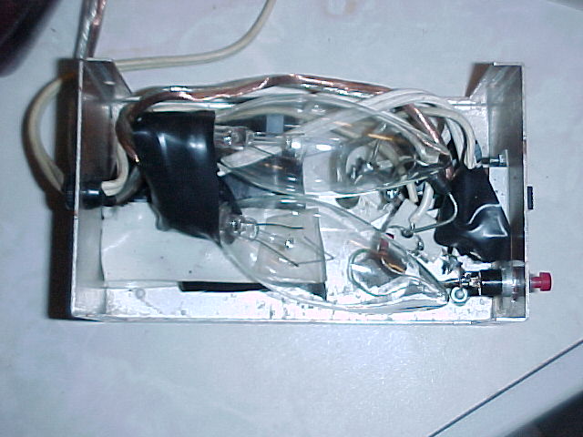
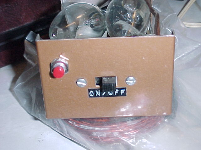
- Pictures of the Original Device.
- Sites of interest.The full Beck protocol must be followed for the pulser to be effective.... Additionally the Blood electrifier should be modified with an extra battery as this has been found to be better with due to variations in skin thicknesses.
You can access the full Beck protocol via:
Build Your Own, For Almost Free, Electromedical Research Devices. Please read related links in this post also.
Stop all processed foods (this includes all vegetable oils (unrefined cold pressed oils such as organic Fax, olive (uncooked only) for salads, coconut and palm for cooking are the only exceptions) and most milk products, unless raw, rest are all adulterated. No breads unless cultured and made from stone ground grains! - Best to reduce carbohydrates and especially salt (but increase raw and cooked organic vegetables) and no artificial sweeteners. If you want a little sweetener go to totally unprocessed ones such as little unpasteurized honey and cane sugar. Take a little lugols iodine say a drop or two a day - don't overdo it.
Also note: dehydrated patients may not respond well to any type of therapy! Nearly all water has toxins in it! Best to use distilled to which a little magnesium has been added. Better to make herbal teas and/or drink fresh vegetable fruit juices
WARNING: This is an experimental device and uses 110/220/240 Volt AC mains voltage, build at your own peril. If not comfortable, have a someone familiar with electronics like a TV repairman build it for you.
Magnetic Pulser: Dr Bob Beck PROTOCOL - short 8 minute video:
Well finally, I have got all the wrinkles out my prototype SCR Thumpy. And this circuit has definitely got the power. You can actually feel an electric current pulse when used in the neck area - uncanny! This is subtle however. I hasten to add that power is not the be all and end all, indeed, it is quite possible to design very effective low power pulsers with exceptionally fast pulse rise times that can surpass the performance of even the most powerful pulser. Unlike the high power pulsers these minimize dangers from electromagnetic radiation. So be warned and don't get carried away with the lure of high power! It has been long known amongst alternate energy and electromedicine researchers that very high speed pulses have the ability to tap into some form of radiant energy that is generally not recognized by mainstream science. Devices with very weak but high speed pulses in nanosecond range have been build and efficaciously used by NASA engineers. This is a well known phenomena and I have worked it out mathematically to my satisfaction. More on this at a later date. One theory is that such weak high speed pulses are able to by pass the cell electromagnetic defences by their sheer speed but certainly there are other issues a play such as tapping radiant energy... For a better description on this please see Dr. Glen Gordon's video here. Dr. Gordon was a candidate for a heart transplant but managed to rebuild his own heart by just such a device.
See also: BIOELECTROMAGNETIC MEDICINE - THE BOOK
Please note that this is not a permanent magnet but a pulsed magnet and as such the polarity is not an issue, when the pulse collapses the magnetic field reverses. Hence one need not worry about the magnetic polarity.
I still don't like the auto types as the body gets habituated to non random pulses the only exceptions are possilbly the natural beat frequency of the Earth magnetic field (9.6 Hz) AND the Schumann waves (7.83 Hz) - a random pulser circuit is still the goal but due to great demand, much against my will, have now included a constant pulsing option for those who requested it. For the sake of simplicity a neon lamp is used. Unfortunately neons are not very stable and tend to vary as time goes by and may need to be replaced so use a socket for a quick change. The pulsing rate can be changed and should be changed every so often so the body does not get habituated, to that end I have added a switch to change the pulse rates...
To calculate the output energy use the following:
Formula: W=(CE^2)/2
W=energy in joules: C = Capacitance in farads: E = Voltage across Capacitor in volts
# capacitors #Joules
5*29
635
741 *Present circuit.
More on Capacitor Charge Calculations is here.Any SCR with PEAK current of at least 600 to 1000 amps should work. The one shown is 20 amp continuous with the appropriate peak rating. The lamps act as current limiters and protect the SCR against a short circuit. The circuit can be further simplified as discussed in point 3 below.
I have build several of these and my experience has been:
1) The capacitors develop a memory and don't fully discharge its better to use a number of them in parallel. This reduces the internal resistance and provides a better result and less memory loss. The caps must be designed for flash applications. They need not all be the same value but must be the minimum voltage rating stated.
2) In the original Beck based designs the flash tube heats and develops some resistance so you need to have enough time between flashes for them to cool down. This has been eliminated in my circuit, however, you still need some time for the capacitors to charge up. The larger the capacitor bank the longer it will take to charge up. Those planning to incorporate the automatic version must be mindful of this and adjust the timer circuit to compensate this effect.
3) Using a high current SCR (forces the caps to fully discharge by providing a longer connection than the strobe) and parallel caps from disposable cameras I can now consistently get 12 - 18 inch jumps with #14 fender washers. You can cycle them very fast (though not recommended). All for less than $30 to $50 Cdn. The most expensive part is the coil which can cost as much a $20 unless you build it yourself! One can further reduce the cost if at a latter date you don't want to upgrade to auto pulsing. This can be accomplished by removing the 10k resistor and the SCR and by simply wiring the a push to close switch in line to the coil. Don't recommend this unless you just can't get an SCR or really need to reduce cost. MAKE SURE THE PUSH BUTTON SWITCH CAN HANDLE THE CURRENT AND IS MECHANICALLY ROBUST!
More info regarding other coils options etc. is available at:
http://www.keelynet.com/biology/thumind.htm
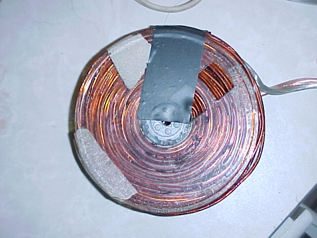
Coil winding instructions from Dr. Beck's paper are:"Junk VHS videocassette reels are cheap, plentiful and adequate for this application. Remove 5 screws from shell, remove reels and discard tape. Be SURE alternative spools (if used) are non-conductive or system will not work. Avoid shorter length VHS tape reels which may have center hubs larger than 1" dia. and won't hold sufficient wire. Drill 1/4" holes through hub and through center of flange(s). Make two 4" discs from 1/4" thick plastic or fiberboard, drill 1/4" center holes and another 1/4" hole off-center so coil's inside lead wire can be pulled through. These 'stiffeners' will sandwich reel's flanges so they won't warp or split as wire pressure builds up while winding progresses. A 2" (or longer) 1/4-20 machine nut and bolt with washers through centers will clamp flange stiffeners and reel and also provide a shaft to hold in a variable speed drill motor or similar winding device if used. Then remove bolt and stiffeners.
Specifications: Completely fill tape spool with #14 or 16 enameled copper magnet wire (130 to 160 turns) wound onto the 1" dia. hub and 3-1/2" OD spool with a gap width for wire of 5/8". Scrape enamel insulation 1/2" from ends and tin. Pull inside end of magnet wire through hub and stiffener and to outside. ~130 turns (about About 1-1/2 lbs should fill spool. Remove bolt, stiffeners, and finished coil. Now solder ends of 3 ft of heavy two-wire extension cord to each side of coil. Finished coil weighs ~1 LB 3 oz, has ~0.935 millihenry inductance, 0.34 ohm resistance, and takes ~20 minutes to hand wind or ~3 minutes with drill motor. An excellent alternative is an AMS brand air-core crossover inductor for home audio, #16 gauge, 2.5mH, 2-1/2" dia., $17.90 from Madisound speaker components.
Those interested in using a 12 V DC source use a cheap 75 watt car inverter I bought one on sale for just $7 Cdn! Simply remove one of the bulbs. This of course is easier if at least one bulb is in a socket.
I have also attached a file for the free CircuitMaker Student Version electronics software for those interested in modifying the simple circuit that I have developed.
Please share your experience so all can benefit. Thanks
Chris Gupta
Sites of interest:
- Here are a few articles on Pulsed Electro-Magnetic Field (PEMF) Therapy.
- Steffan Heydon' Home-Made Bob Beck Electromagnetic Pulser based on this basic design.
- Bil Green's M-Pulse 5000 with lots of supporting info.
posted by Chris Gupta on Thursday February 19 2009
URL of this article:
http://www.newmediaexplorer.org/chris/2009/02/19/build_a_low_cost_simple_magnetic_pulser.htm
Related ArticlesMigraines
At 09:36 2009-02-11, Gerry wrote: Hi Chris Could you please give me the remedy for migraine headaches, my wife gets these consistently!! You had mentioned organic yogurt mixed with what I forget?? Thank-you ------------------ Hi Gerry, Here is a little compilation (not complete by any means) of remedies: Making the Magnesium-Migraine Link In addition to magnesium, get some live organic yogurt and add a capsule of Vitamin B100 complex plus... [read more]
March 02, 2009 - Chris GuptaBuild a Low cost & simple Magnetic Pulser
Finally, at long last here is an extensive update (of the 2003-08-19 original) that many have been requesting. Some additions are: - Basic 220/240 Volt AC Circuit. - A Simple auto pulsing Circuit. - 12 V DC Operation - High Power vs low power - discussion - Polarity of Coil. - Various other embellishments and updates - that should address many questions in the comments - Pictures of the Original... [read more]
February 19, 2009 - Chris GuptaCell Phones - Ear, Eye Damage, High Blood Pressure & More!
Further to: Em Fields On Brain Tumor Incidence - Chemicals And Cell Phones ... here is more incriminating data. This adds to the already copious data on the negative harm from EMF (Electro Magnetic Radiation). Just as EMF can help in some instances so can it harm if used inappropriately. The microwave 2.4 mhz as the 60 Hz* mains frequencies are one of the most harm full ones. Surely... [read more]
August 22, 2007 - Chris Gupta
Readers' Comments
Following is some feedback I recieved regarging the use of this device.
Chris Gupta
Date: Tue, 10 Jun 2003 04:34:48 -0700 (PDT)
From: sergio masiddo
Subject: YOU ARE SAVING LIVES
....THIS IS THE SECOND DAY I USED YOUR MAGNETIC THUMPER ON
MY BRAIN......YOU ARE SAVING LIVES......THERE IS 98
PERCENT REDUCTION OF PAIN AND DISCOMFORT...
THE GOOD LORD RECOMPENSE THEE
SERGIOPosted by: Sergio Masiddo on August 19, 2003 03:50 AM
Cris. I have a sota puler that is not very strong as you know. It is effective to a couple of inches?? However I have also a magnetic waist belt that I use against my skin witht he pulser on the other side. Boy does that pack a whallop and it does the job in a few zaps. Need to have some professional attention to this method of inhansing the pulser to penitrate deeper . I have used it on the sinus area on my head with great relief.alson on kidneys same results. Gods speed and keep the reaseach going. The Truth will set you free owh.
Posted by: O W Hungerford on August 24, 2003 03:42 PM
Wir brauchen Ihre Hilfe.
Ihre Beschreibung MagneticPulser die Windungen
(130) Querschnitt der SpuleGerhard Ditterich
Weistfeld 17
30539 Hannover
Germany
T +495119524360Posted by: Gerhard Ditterich on October 4, 2003 08:20 PM
Tjarko, what is Maximol and / or NewVera?
Also it is not always true that the "problem will move to anther place" as the magnetic pulse or electric currents change the profile of he cell membranes that facilitate nutriment uptake and detox that can heal the injury pronto....
Posted by: Chris Gupta on December 5, 2003 06:15 PM
dear Christ, I'd like to know if can tell me which changes should I make to the circuit for use it al 220 v 50 hz. Is there any other automatic pulser that i caN built?
Thanks
josePosted by: Jose Podadera on December 7, 2003 01:25 AM
just checking to see if this comment section is working again...
Posted by: David Waggoner on July 7, 2004 06:36 PM
Creative Science & Research
PO BOX 557
New Albany, IN. 47151www.FuellessPower.com
sales@fuellesspower.comPosted by: David Waggoner on July 7, 2004 06:38 PM
Hi, it would be nice if you could post some pictures of the final project/board. Though a schematics is fine then for me it would be easier to also have a picture to look at.
Thanks for your great site.
Posted by: john on August 24, 2005 04:11 PM
Hi, I bought all the parts today which was pretty easy except for the SCR.
3 things:
1) shouldnt i put metal inside the coil to enhance its effect?
2) I have used 6x 560 UF capacitors (at 250 v) for the unit - will that be ok when I use 250 volt? I wanted to make it more powerful than your schematics (also, i could not find any capacitors lowwer than 270 UF anyway). Or, should I increase the capacitors to capacitors who can handle 400 volt instead of just 250 volt?
3) Your schematic is good. You could make it more clear your text because sometimes it seems like you talk about a schematic/part of a schematic which is not on the page, other times you talk about schematic 1 or 2 - and its not really clear for a newbie at least :-).
4) pictures of your units would be a great enhancement also.
Posted by: john on August 25, 2005 06:39 AM
I have built a super thumper with 4,000 uF of capacitors. I used a huge SCR. When the coil is set on the floor with an aluminum washer it will launch the washer into the ceiling leaving a dent. Two or three pulses and arthritis is gone! The schematic is under electromagnetic coil devices on my web site.
Posted by: Bob Davis on August 27, 2005 05:04 PM
Hi, make sure that if you use 220 volt instead of 110 volt that the capacitors can handle at least 450 volt.
Also, be aware that the click switch should be made of very good quality - mine blew off afer just 1-2 clicks (where I did not use the SCR also).The SCR is probably a very, very good idea so now I am upgrading my simplified version to the one with the SCR. It should be finished by tomorrow...lets see how it works then :-)
Chris, thanks for your help about modifying to 220 Volt.
NB Please make updated schematics to make the magetic pulser oscillating wth 5.000 hertz or similar.
John
Posted by: john terry on September 6, 2005 11:49 AM
John, it is not possible to oscillate at 5,000 hertz at those power levels. The oscillation is limited to the recharge time!
Posted by: Chris Gupta on September 7, 2005 12:10 AM
Chris, I have a design schematic for a pulser that can auto-pulse at 1 and 5.000 hertz. You can ask "V" to get it or me.
Posted by: john on October 2, 2005 04:05 PM
Please sent it John, will have a look. Incidentally you cannot pulse at 5000 Hz at the powers here unless you have a humongous power supply!
Thanks
Posted by: Chris Gupta on October 3, 2005 12:00 AM
Hi Chris, 12.Nov.2005
I have used your schematic to construct a Magnetic Pulser. I am not wonderfully electronically minded; I try to follow the picture. I will try to include some pics with this email. If they do not come through, let me know how to get them to your site.
I was unable to get a 130uF capacitor, so used a 100uF @ 160v. I used, used PhotoFlash capacitors from disposable cameras and had an assortment. I firstly used 5 120uF (= 600uF) at 330V. I attached it all to a simple board. My SCR is 600v 25 A.
I had some problems. Firstly, I had wired up the SCR incorrectly, so it was not happy. (Thought that the gate was the middle terminal, not the # 3 terminal. Had to have an electronics friend help for that.
Secondly, I did not clean up the board well enough and caused a small burn across some connection, which were too close to each other. (Photo 1: Note the board scorch beneath the SCR.) I removed the SCR from the board as it gets warm with rapid use. I also changed the position of the rectifier (2N5402) as it was too close the PhotoFlash-legs connector.
It did not thump as well as I expected, so I added another 2 PhotoFlash capacitors and all was well. Total PhotoFlash capacitors now 860 uF @ 330v. I mounted the bulb, (100w) in a separate container to reduce the heat and for protection against a capacitor exploding.
The SCR and the capacitors get very warm when operating at peak times. It takes about 2 seconds for the lamp to go out ( recharge the capacitors). I now fire it between 4 and 8 seconds intervals. The thump is quite noticeable.
I used heavy duty flex from the works to the coil. I am presently in Mexico, so I sometimes have problems getting the locals to understand my bad Spanish and have to use internet pics to order difficult parts. (I have also just completed a Beck Blood purifier � and it is working.) For the coil, I used 16 gauge enamelled wire about 150 turns � with ample silicon, to prevent movement and shorting, (ordered #14 gauge, but #16 arrived). I also covered the back of the board in silicon to prevent short outs between the PhotoFlash capacitor legs. As they were already used from the cameras, their legs were short. I used heavy copper wire to connect each. Next time, I would probably use insulated wire and break the insulation at the leg points. The coil is in a plastic container. My wife and I have only been using it for couple of days, so we will need a little time to determine its efficacy. Photo 2 complete in plastic containers, yellow momentary switch and the thin plastic cover of the coil, kept open with the pliers.
I now have a few questions for you, please.
1) Will the thickness of the coil container make much difference to the coil output?
2) If I were to add additional PhotoFlash capacitors, do I need to change either the SCR of the primary 100uF capacitor? I was able to buy an SCR 600v 40A today. And could probably get an 800v 40A, now that I know the manufacturer and ordering numbers.
3) Could you let me know if it is possible to use something like the flash bulbs of the disposable cameras to not have to use the 10w large globePosted by: Al on November 9, 2005 11:34 PM
Hi! Cris could you tell me please the difference between a Photo flash capacitor and Electrolytic capacitor. Will they work just the same on the magnetic pulser circuit?
Thanks,
RicardoPosted by: Ricardo Macalino on November 21, 2005 11:35 AM
Cris, Could not find SCR here would a TRIAC work in place of it in the magnetic pulser circuit? Thanks again
Posted by: Ricardo Macalino on November 21, 2005 09:39 PM
please send me pulser circuit of ultrasound.
Posted by: semsem on November 26, 2005 12:53 PM
Georgia,
Please read:
Posted by: Chris Gupta on November 29, 2005 03:24 PM
Hi Chris, 02.Dec.2005
I emailed you Nov 12 to this forum, but I believe that I messed up my new email address, which I have now amended.
I hope that you may be able to find time to answer some of my questions from that November post.
With thanks
AlPosted by: Al on December 3, 2005 12:53 AM
A transformer just adds expense. The idea was to make as cheap as possible.
Yes I have designed a timer but just have not updated it yet.
The circuit is self limiting hence there was no need for adjustable current.
Posted by: Chris Gupta on January 13, 2006 12:22 AM
What is the function of the 120 Volt, 120 watt lamps or 2 - 60w lamps in parallel? Circuit Voltage dropping?
Should they be be replaced by a resistor of the same wattage.
Does the inductor to the right side of the schematic circuit represent the magnetic treatment loop?
If so, what physical size is the treatment loop?
What is the function of the The 10K resistor the Diode and the manual switch in the top schematic?
The link to free Circuit Maker Student Version electronics does not transfer to the link.
You should reduce the horizontal length of the circuit in order to print the whole circuit with out resorting to separate landscape printing.
Read your reponse re previous question series and have the following comments.
No transformer may be less costly, however, it will make the circuit more effective (gause wise) and provide a control range which I would consider necessary for treatment of the immune areas over the heart.Posted by: Anders Anderson on January 13, 2006 09:41 AM
I have examined your circuit more closely and now found the answer to my previous question regarding the inductor.. And find in your preamble, this induction coil is wound on to the Video Cassette.
However, you have not shown the "Therapy Loop" as a device in your circuit, Is it in series with the Induction Circuit?What amperage would one get in the therapy loop?
Posted by: Anders Anderson on January 13, 2006 11:35 PM
Anders,
There is no need for xformer it will not make the circuit more effective. Study the circuit more and you will have the answer.
There is no "therapy loop", it is designed to be used as per the Beck protocol.
Please reread the information before asking more rhetorical questions.
Posted by: Chris Gupta on January 14, 2006 11:01 PM
Mike, that is normal. It all depends on how precisely in the focus of the feild you place the washer.
Posted by: Chris Gupta on May 22, 2006 12:24 AM
It seems to want to attract metal
more than repel. I put one of those nail grid arrays next to it
and it attracted all the nails.
maybe my coil is not precise as I just used a speaker coil with 2 ohms resistance.Posted by: Mike C on May 22, 2006 04:58 PM
please let me know where i can find these schematics that everyone is talking about on this page.thanks
Posted by: marinus gerber on May 29, 2006 01:14 PM
Ken, you can use the 250 v caps, although your will be pushing them. The two light are needed for safety and there is no cheap way to replace them. Resitors are not suitable.
Posted by: Chris Gupta on June 9, 2006 11:50 PM
Hi Chris; have built the pulser. used five 350uf 450v cps and a 220uf 350v after the bulbs. used two very small halogen chandelier bulbs under a small mason jar on top of housing. a 15a micro-sw for the trigger. when I fire it up the bulbs light and go out in about 1.5 seconds and when triggered get only a weak pulse that barely rocks a 1.5" washer. Should the caps be closer on value to the schematic? I did the scr one.
Posted by: on June 15, 2006 12:48 PM
What wattage are the bulbs?
Posted by: Chris Gupta on June 15, 2006 03:56 PM
Dear Chris,
The link to circuitmaker is not working... can you please send me the JPG of the circuit with the modified SCR version ??
Regards/Mohammed HarisPosted by: Mohammed Haris on June 27, 2006 07:51 AM
Los bulb de 120 w es un foco de filamento de 120 w normal de los que se usan en casa
Posted by: Javier Camberos on August 8, 2006 09:02 PM
Hello
Could I inquire Chris 7hVhycis their a modulaing frequency that would be most beneficial.Than you
Ray
Posted by: Ray on September 4, 2006 06:06 PM
hi chris. I wud like to build an auto-pulser. May you please send me a schematic and intsructions to help me building one. I have all the components to build one. Thank you for your help Chris, it is very invaluable.
Posted by: Admare Jinga on November 16, 2006 05:37 PM
just checking to see if this comment section is working again...
Posted by: steffan Heydon on November 14, 2007 01:51 PM
can you tell me the frequency of the magnet pulser you have designed.thank you from jason.
Posted by: JASON MORGAN on November 23, 2007 11:26 AM
Photos with basic electronics info related to the construction of Chris Gupta's Electromagnetic Pulse Machine can be found on my web site. The information presented, will be invaluable to anyone wishing to construct their own electromagnetic pulser (thumper). http://www.twotowers.com/beck/beck_emp.html
Posted by: steffan Heydon on November 25, 2007 11:07 AM
Build a new Thumper and got some very interesting results with it. I use a bridge rectifier on a 240Volt supply. In series with an oven element of 2.2 KW to limit the current. Originally I used 3 650 uF capacitors from old photo flash units, the SCR is rated for 30 amps continuous. Now with the total capacity of 1950 uF I had a reasonable strong magnetic field. I then replaced the photo flash capacitors with high quality elyt capacitors. Also 3 X 650 UF. They are not flash rated but are very large indeed. They have screw terminals on top and are the size of rather large jam glasses. The interesting results are as following, the capacity is the same but the large capacitors actually generate pulses which are may be 50 to 100 times stronger as the flash capacitors. Also I noticed that after 30 to 40 pulses the coil gets so hot that its impossible to hold her in the hand. Also the original capacitors got rather hot after a few discharges, the big capacitors stay completely cool. One thing I have to be very careful is to keep the coil away from monitors or television receivers. During the first tests it magnetized the shadow mask of my monitor from a distance of more then 6 feet. I had a hell of a lot of work to do to degauss the tube. What I do not understand is that the overall capacity is the same, but the results are spectacular different. Best Regards
Posted by: Jurgen Vogel on January 7, 2008 11:34 AM
What would be the modifications of the magnetic pulser for 220v AC? Thanks.
Posted by: Eduardo on February 4, 2008 08:13 AM
Chris, can you please give me the modification for 240VAC version of your pulser? Thanks
Posted by: ALFONSO on February 13, 2008 02:46 AM
Chris I would like you to publish a 220-240VAC schematics..You are saving lifes here mate, please do the necessary alteration as soon as possible!Please! If Chris can't do that, please anybody else who knows how to do it, please do it!Just give us a complete schematic for 220VAC with parts etc. and I persoannly would be grateful!Thank you in advance
Posted by: Nick on March 27, 2008 10:39 PM
Are there any hobbyists out there willing to make a thumper/godzilla/beck pulser unit for me at some cost? I can be contacted at my URL. thank-you.
Posted by: HMK on April 3, 2008 11:20 AM
Hi Chris, I finally was able to get a S6020�.had to order it and it took over a week to get here. Your Thumper works beautifully�washers were hitting the ceiling. Many thanks Chris....you're a legend. Kind Regards, Lothar
Posted by: Lothar on April 4, 2008 06:08 AM
Hi Chris, I am interested in the 220-240 Volt version schematic if it is available. I read a previous post, shown below, and would like to also get the details if possible. Regards, Terry "Hi, make sure that if you use 220 volt instead of 110 volt that the capacitors can handle at least 450 volt. Also, be aware that the click switch should be made of very good quality - mine blew off afer just 1-2 clicks (where I did not use the SCR also). The SCR is probably a very, very good idea so now I am upgrading my simplified version to the one with the SCR. It should be finished by tomorrow...lets see how it works then :-) Chris, thanks for your help about modifying to 220 Volt. NB Please make updated schematics to make the magetic pulser oscillating wth 5.000 hertz or similar. John Posted by: john terry on September 6, 2005 11:49 AM"
Posted by: Terry Ross on May 26, 2008 10:50 PM
Greetings! Could post the 220V plans please ))
Posted by: Alex on June 10, 2008 12:35 AM
I can convert any schematic or plan to 110,120,220 or 240v.
All... The key to conversion is the total POWER (in Watts) which is a product of Volts * Amps into the device.
Diodes and Capacitors must be rated 2.5x the input voltage. Actually it is 1.414* but then they tend to overheat. I always use 250-300v for 110/120v and 600-800v for 220/240v. A TIP:
Photoflash capacitors are designed for High-Voltage, LOW current, very quick 'low-load' discharges. A photoflash tube (Xenon) is essentially a glass tube filled with Xenon gas and an electrode at each end. The Gas is inert/does not conduct electricity, hence it can be put directly across a fully-charged set of 350v capacitors and will NOT flash. The 'secret' is a tiny transformer of 80:1 ratio, which has its output wire physically 'wrapped' around the Anode-end of the xenon tube. When 'Fire' is pressed, part of the energy srored in the capacitors goes thru that tiny 'trigger' transformer and comes out 80 times higher (350v*80=28000v) This High Voltage Ionizes the gas in the tube (turns it instantly into a conductor) and a 'short circuit spark' jumps from the Anode to the Cathode, creating a bright flash. Very little to 'No' load there, huh? A coil on the other hand, cannot be put across the capacitor because it WILL spark loudly, short out and commpletely drain the 'Cap, and produce a massive magnetic pulse. It is for this reason that an SCR (Silicon Controlled Rectifier) is used. It CAN handle the massive short-circuit current flow of the coil device. Further, an Electrolytic Computer-Grade capacitor is larger, heavier, much beefier and can store many times the ENERGY as a similarly-rated Photoflash device.. which is why your Lyticaps THUMP better ;-)I have built a Zapper of my own design, producing perfect square waves(!) from .01Hz all the way to 40Khz @ 0 to 300ua, using only 1 IC and 4 electronic component parts. The first one I made was back in 86; and still works, although I had to replace the batteries numerous times along the way. It is 3*2*2", uses only 2 3v batteries and the 'tingle' can be felt through the entire body, from Head to feet when one steps on one wire, and bites a spoon connected to the other.
Now I am perfecting a Thumper which anyone can make from a discarded Auto-Flash camera and a bit of time. I managed ~30 such cameras in several diff. configurations and models and am on the case!
Stay tuned
PM me if you want to chat or need helpPosted by: Supertechster on July 15, 2008 05:58 PM
Supertechster Re: "I can convert any schematic or plan to 110,120,220 or 240v." I am very interested in any info you may have on this 240V conversion. But - where do i PM you ?? Terry Ross
Posted by: Terry Ross on August 6, 2008 10:51 PM
Why is everyone increasing the capacity of their "thumpers" to such high levels, when the original Beck model was designed to create a specific micro current? This would seem to me to be straying away from the original model which worked fine.
Posted by: Phil on August 16, 2008 07:34 PM
HI Chris...thanks for you generous sharing..I been trying to build one of this ..but Im in New Zealand and 240V are not working for me ., the firs capacitor keep blowing out on me with a big BANG...mast said is a 100/450V and for the main I use a 1000/450V can't find the proper SCR got one that looks like a thryed three legs ..from I think the first is the anode second the catode and last one the gate ..if no maybe is way it does not work for me . so skeep the SCR and fired it and works the first maybe the second time and then just stop the diodes just short out so has been very desapointing ..I will keep trying..probably Im just dam as never try before any electronics...yes i know find someone else to build it ..but is not the same ..can you please give some advace especialy on the 240V and the SCR as is the only one that I been able to find over here.. and is a 800V at 35A...any help will be apresiated from anyone that use the same voltage GOD BLESS ALL. from Joe.
Posted by: J ZEPEDA on August 19, 2008 09:19 PM
I would like Supertechster to get in touch with me.
Posted by: Carl on September 27, 2008 01:50 PM
Hello Chris:
I am confused about how to attach the extension cord wire (or speaker wire) to the coil itself. Beck explains:"Now solder ends of 3 ft of heavy two-wire extension cord to each side of coil"
Does he mean that the ends of the coil wire are attached to the ends of the cord wires or soldered directly to the sides of the coil?
Thanks for any help
Response: Yes.
Chris
Posted by: Todd on November 12, 2008 09:52 PM
lol, Chris, I had an 'either or' question and you answered simply 'yes'. Could you explain a bit. Thank you.
Posted by: Todd on November 14, 2008 05:32 PM
Hi Chris thanks for putting up with all us electrophobs for many years now. Can you explain for me, how it is safe and not straight mains going threw the coil that would be dangerous. Can you provide a working 240V version diagram, I have now trashed 3 battery flash versions and wish to upgrade but am afraid of the mains connection. Thanks for being.
Posted by: Stephen on December 11, 2008 06:56 AM
Hi, With regard to the 240 volt operation you should all be aware that lone capacitor at the beginning is forming a voltage Doubler, so removing it and shorting it out would lower the voltage to similar to the that intended at the capacitor bank. I would also put the bulbs in series if they are 110 bulbs. Although I have not tried it so take care, and at your own risk of course.
Posted by: jon on January 13, 2009 08:58 PM
is there any step by step program to build a really powerful pulser? I can read schematics fairly well but am not electrically inclined enough to know what the parts look like or where they go...Any info you can give me would help...thanks in advance for your time..Frankie
Posted by: Frankie DeLong on January 30, 2009 01:16 AM
Hi Chris. I am getting some parts together to build one of these units myself. I live in England so I need to use it on 240v. I have sourced the capacitors, I have 5 80uf and 2 or 3 120uf, can I wire them all in parallel, or do they have to all be the same rating? Is 330v enough of a top end so that the photoflash caps don't blow. And third-ly, is Jon ^^^ right about the first capacitor near the bulbs being a voltage doubler and I can leave it out. I don't want to blow myself up or electicute myself as you can understand. I have/did have colitis (I'm going for a test next week) before I started using my flash gun magnetic pulsar and plant stimulator, now some of the symptoms are disappearing. I have got together a 10k 3w resistor for the SCR, a 3 amp push to make switch, a couple of 1n5406 diodes (rated 600v 3 amp) and a UH20FCT (which is the SCR) rated at 300v. Does it look like I'm on the right track? Or do I need further help wiring this for 240v?
Posted by: Paul Sumner on February 1, 2009 10:17 AM
A message for Todd, further up the page (Nov 12 2008 - yes I know it was an age ago). You strip back the insulation from the copper wire from the start of your winding and the end of your winding using sandpaper and solder the mains wire to each end of the winding you have just sanded. Imagine your coil as a resistor, as it were, wiring it in series.
Posted by: Paul Sumner on February 2, 2009 06:17 AM
For 240v op I used a 240 to 120v transformer to power it as is without changing anything, works great.
Posted by: Peter on February 7, 2009 11:05 PM
Paul, I am sure of the front capacitor forming a voltage doubler, the problem is at 240v the voltage on the caps is still a little too high for 330v caps suggested they need to be at least 350v with the voltage on the cap going to approx 1.414 x the quoted mains voltage, 400v caps are safer. A transformer is a more conservative approach, if you are at all worried then as 'Peter' a says transformer is the answer. For everyones information for a given capacitance if you double the voltage the joule energy quadruples therefore if you run the original circuit at 240v with all capacitors voltages suitably scaled i.e. voltage of caps x2.5 you can divide the capacitances needed by 4. However at these voltages the device become much more dangerous, so I would favour a solution keeping the voltage stored lower. All the above info is of course my opinion, and is offered in the spirit of friendship FOC, but of course used at your own risk.
Posted by: jon on February 8, 2009 07:31 AM
They sell 100w step down transformers on ebay for about £15, or 300w for £27. Don't think 100w would be powerful enough but would 300w suffice? Not sure what the amperage is of this beastie! I assume that it's at least 120w because of the 2 bulbs. Also if you visit http://www.twotowers.com/beck/beck_emp.html and view Steffan's pulser he put the live wire to the switch which seems to go straight to the coil! Live to coil looks v dangerous. He said that a switch should always work on the hot wire, which I agree. But if you look at the diagram, that would lead the live to the coil, with no diodes blocking. This would either shock you or just turn the coil into an electromagnet without firing it off. Anyway, not sure if Chris's design should have the switch just between the bulb and power as I would not normally wire a bulb to the neutral wire alone and to go through all that circuitry to get the live back or maybe Steffan is correct? He did say that it may not matter about the polarity. After all it is AC and the nature of AC is that is loops from plus to minus. I don't fully understand that though because in that case then why can I not get a shock of a neutral wire, but I would always get a shock of a live wire. Then there's something I read recently that a switch should always be at the end of a circuit. The only problem is if I do get a stepdown transformer I would have to source 2 X 60w 110v bulbs and I'm not sure about the diodes, would the higher voltage ones still block a reverse current? Still at 21p a diode I may as well replace them eh? The bulbs seem harder to get, unless they are from china.
Posted by: Paul Sumner on February 9, 2009 07:00 AM
Actually the bulbs exact bulbs are not too critical. They appear to be acting as a simple charge current limiter.They also stop shorting the mains when you fire the trigger too. I would say that the power drawn can be no more than the that of the bulbs, since they are in parallel, it seems that 120 watts is the max power, however in theory you might need too have a bigger transformer as the effiency of the tranformer is not 100. If you use lower Wattage bulb or bulbs the circuit will work just the same, the transformer can then be cheaper and smaller, the only difference would be is that it will take a bit longer to recharge the capacitor bank between each discharge, which I would have though would not be a problem. The orginal circuit should still work with only one bulb and create less stress on the diodes and caps in the process. I will comment on some of the other stuff in your post when I get time to check it out.
Posted by: Jon on February 11, 2009 07:04 PM
i would just like to ask chris or anyone here i just built my first pulser and used old school modified camera flash. the flash is a vivtar 2000 model, what the power from a flash like that will produce out of the coil? and second when i discharge the flash there is definitely a pulse coming off the coil but the flash is not any dimmer than usual, does that mean most of the power is not getting dumped to the coil?
And also to anyone who doesnt want to wind the coil, the msm electronics is no longer selling them, but I found a company that does sell almost all size, gauge, and mH coils
Posted by: bryan on February 12, 2009 03:45 AM
And also to anyone who doesnt want to wind the coil, the msm electronics is no longer selling them, but I found a company that does sell almost all size, gauge, and mH coils http://erseaudio.com/
Posted by: bryan on February 12, 2009 03:45 AM
Nearly there now guys. I tried wiring the scr every which way then gave up and bypassed the SCR and resistor. Pop, the washer jumped!! YAY!! BUT..... The SCR is good for holding the power down until it dissipates as I found out when I got a shock. I'm still here! I needed that!!! Anyway I could do with some help with alternative SCR's please and how the 'ek you wire them. I am quite naughty! Coz I ignored some peoples advice and went for wiring it up for 240v. Sorry Jon. What I did was wire everything by the diagram with the live going to the switch (even if I don't really like that, I would prefer the switch to go just before the bulbs and to wire the live that way round.) Because if this has been build 100s of times before it must be right! Anyway the secret was to wire the capacitors in both parallel and series. + to + and then - to + and + to the next - on the next cap. I got 660v rather than 330v that way, which I admit is fooooookin dangerous but it works, and there is no chance of the caps blowing that way. All capacitors ran cool and my switch has worked a few times, I'm not planning on using it much without the SCR as I don't think it's as safe without it. My smoothing capacitor for the bulbs is a single 120uf 330v (I worked it out because my other caps are 660v) If you look at Chris's brill plan the first cap is 150 v and the capacitor bank is 300v so to me 330 and 660v seemed perfect. My problem was that my SCR would not feed the caps. I had a multimeter placed accross the capacitors initially to watch them charge. They charged in about 1-2 seconds the first time then less then a second following that. When I pressed the switch (with a plastic ruler) the coil thumped and lights flickered and went out. I then unplugged the device and watched the multimeter, back up to 660v so I pressed the button.. Thump again. Then I think the single capacitor must have been charging the bank because the voltage went up to 330. This circuit as it stands is v hard to discharge. I have left it upstairs with a massive resistor across the cap bank. Another question is when unplugged the actual plug seems to get a charge from the 330v cap! I put a multimeter across and it read about 330v? Whats going on, should it do that. I will say that I left the power switch in the circuit on, maybee that has a lot to do with it. Please advise. I know I'm a monkey for playing with 240v (or 660v)but at least I know it works, and I may as well persevere with it. Another question I have is when you see Bob Beck with the coil he actually puts his tongue on it and presses the trigger. Stupid question (I'm not about to put my tongue on it now),but does the coil now need to be heavily insulated so that I can hold it, or is it still just a magnet that can't harm me? I have put insulation tape around the connections to the black box, but just simple sellotape (for now) around the coil, mainly to keep it together. Paul...
Posted by: Paul Sumner on February 13, 2009 07:57 PM
Hi Chris, I am new to this magnetic pulser circuit but decided to build one. Here in South Africa our mains voltage is around 230v. Obviously the input doubling cap and diode can't be used on 230v. I used two 60w 230v bulbs in parallel .I wanted to use 100w but couldn't find red ones in that wattage! Red ones look nice! The bigger the bulb wattage the quicker the charging. The capacitors I could get are rated at 330v ,which run at full voltage. They have not shown any distress at this potential so far and work fine. A 400v rating would be better. The capacitors add up to about 800uF and I have used a 40TSP16 thyristor which runs very cool. After using for a while I got tired of repeatedly pressing the trigger button and built a simple circuit to trigger the coil every 7 seconds and switch it off after 20 minutes. This is much better and more relaxing to use! To answer some of the readers' questions. The position of the switch in the live or neutral does not make any difference as the coil will be completely insulated and the components mounted in an insulated box. As the circuit is directly connected to the mains it must be unplugged anyway if work is to be carried out .Also the capacitor must be discharged , I use a 820 Ohm 10 watt resistor. A cheap and cheerful way to reduce the voltage a little on the caps is to buy 20 cheap 2amp 1000 piv diodes and wire them in series in place of the regular diode .This will effect a drop of about 12volts which can be useful. They can be soldered together side by side and take up very little space. Brian.
Posted by: Brian on February 14, 2009 09:01 AM
simply put, i want to build a thumper. i have some knowledge of electronics and can read schematics but i have trouble applying what i see in the diagram ( which i can read ) to actually building it. where can i get a complete list of parts and where to get them? what is the diameter of the copper coil wire to make my own coil? anyone that help me out? i have a medical condition that i want to try one of these on because im tired of surgery. any help that anyone could give me would be great ...Thanks and God bless...Frankie
Posted by: Frankie on February 14, 2009 11:44 AM
Anybody who can send me the Schematics of 240 will be wonderfull. Bob Davis of "I have built a super thumper with 4,000 uF of capacitors" please send me the Schematics as the link you gave doesnt work. I will appreciate. Please Jurgen Vogel also send me yours too, i have a look at them.
Posted by: Jackson Mungai on February 18, 2009 12:39 AM
Well Done Paul, there is more than one way to skin a cat. I was going to point out the option of putting the caps in series to increase the voltage,(this does have the capacitance however) but had descided to try and guide you towards a lower voltage and probably safer device. With the extra voltage I would consider lots of insulation essential! I was interested what bulb you used ?
Posted by: Jon on February 20, 2009 01:48 PM
Hi Chris, still saving lives and freeing us from surgeons and doctors I see. I have to say, I've tryed your 240v version, it works well, but does not charge half as fast as my 240vac to 660vdc version. I have sussed out why my scr is a bit dicky. I got a new one from RS and I just needed to wire my 3 amp 10k resistor as a 6amp one by putting 2 of them in parallel. The scr could not read the lower voltage properly from the switch. Thus the caps would charge but when I pressed the button the thumper would not fire. Try it if your having problems with 240v folks. It also works with 4 amps (2 x 2a) and 5 amps (1x2a and 1x3a) sometimes work, but definitely not with an inverter stepping up the volts from a 12v car battery. I've also discovered that since I took the charging cap (the first one near the bulbs) out of the equation and the diode, as per your diagram and stepped the voltage down to 330v, the thumper wont build up enough charge across the capacitors to activate the scr-whilst using my inverter/but will on mains power. But my scr may be too big as it was rated for the 660v circuit. Anyhow, what I have learned from this exercise is that the higher voltage of my original design does not increase the thump, but because of the first capacitor and diode that runs across the caps, it does charge up almost 3 times faster. I'm sooo boring!!! Paul...
Posted by: Paul Sumner on February 20, 2009 06:20 PM
Hi Folks, please can you tell me what the A/B switch is. Is it a user operated single pole double throw toggle? Or double pole single throw? And are the 1M 70 percent and 1M 50 percent just 2 X 1 megaohm potentiometers set to 50 percent and 70 percent resistance? These may seem like stupid questions, but I just want to be sure. I take it when the neon lights up the signal is sent to the SCR triggering the pulse off??? Very ingenious Mr Gupta! I wish I could create circuits like this. By the way, I sound sarcastic, but I'm serious. Thanks Paul...
Posted by: Paul Sumner on February 22, 2009 07:05 PM
A word of caution Jackson. To much power can cause the coil to give off electromagnetic radiation. Please don't use too much power. Chris has mentioned it at the begining of his article. All Bob davis uses his pulser for is fun, i.e throwing hard drive plates 40 foot in the air. He uses a microwave transformer and 700volts, the apacitors look about as big as coke cans. You can watch him on youtube http://www.youtube.com/watch?v=2M3rzx6jtnk&feature=channel_page As far as I'm aware if you were to zap yourself with this you are likely to fry your internal organs with radiation!
Posted by: Paul Sumner on February 23, 2009 02:02 PM
Dear Chris Can you email me a schematics for a 220/240 autopulse circuit magnetic pulser "thumper" I would be eternally grateful, I need it for a serious health problem urgently. Thank you Charles
Posted by: Charles Bayl on February 24, 2009 06:24 AM
http://www.geocities.com/bobdavis321/ Bob Davis's website.^^^
Posted by: Paul Sumner on February 24, 2009 02:28 PM
Hi Cris, Thanks for your efforts. I find that my unit works well enough and thought the output was week with it building up to 247 volts peak across the three 270 uf caps in parallel so I decided to put a speaker magnet on the back side of the coil (away from treatment area) and it really improved the pulse for the first pulse but it de-magnatized the magnet, so if anyone else has experimented ways of increasing the shape of the magnetic discharge to effectively shape the pulse towards the treatment area and not de-magnatized the magnet, let me know. also thanks of the tip of using MSM for eyedrops to increase eye hydration for cataracs
Posted by: David Spiller on February 25, 2009 09:07 AM
I managed to build an autopulsing circuit with 240v. I combined fog 3 with fix 4. It works quite well, although because the pulsing is quite fast, the capacitors don't charge as fully, so it's weaker. I'm going to go for modifying my 660v capacitor version with a 220v neon (or a neon and 270k resistor in series) 2 X 400v 10uf caps in series (for the pulsing circuit to bring the capacity up to 800v) and my 330v 120uf first cap with the 2 diodes in place. I will keep you posted as to how that all works. The 240v version Chris has so kindly posted does not seem to charge as fast as my series capacitor version, I think the first capacitor near the bulbs and the diode linking the live wire up to that capacitor in order to charge it is really needed, it helps the capacitor bank charge faster. Cutting those 2 components out of the circuit makes the pulser either slow to charge, or week in the multipulser circuit. I still think the series/parallel caps work better ie 4 capacitors of 130uf/330v each wires in series and parallel would in my circuit equal 660v 260uf 2 of them in series would be 660v 130uf or if you did them in parallel 330v 260uf. Does anyone know what I mean by series AND parallel together to double the voltage AND capacitance? I have taken some pictures of my capacitor bank and will hopefully post them somewhere for you.
Posted by: Paul Sumner on February 26, 2009 12:18 PM
Can someone send me schematic drawing of the 240V autopulse circuit. Also where can I purchase a circuit board for the bob beck blood zapper. I desperately need this, please help! regards Charles Australia
Posted by: Charles Bayl on February 26, 2009 11:13 PM
At the top of this page http://www.newmediaexplorer.org/chris/2003/08/19/build_a_low_cost_simple_magnetic_pulser.htm is a set of 4 schematics. #4 is a 220/240v version of the Thumper. The basic difference between the 110/120v and this one is removal of the voltage doubler ckt (1 diode and 1 capacitor) To increase the output, simply add in additional capacitors across the 5 130Uf/330volt ones already shown, bearing in mind that there is a limit where the joules will fry the scr and blow the coil. OK.. Coil is air-core spool with 2.5Mh inductance and avail at good Audio suppliers on line, Farnell, Dick Smith in Aust. or CPC /Maplin in UK. The author and several of the responders also provided links. For those of you new to DIY Electronic assy, 90 of a 'parts list' to take t the parts store, can be derived from the schematics... You will need: 1ea 220v fused ac cord, 1ea heavy duty switch to handle 2-5 Amp inrush current, 1 or 2 tiny 220v bulbs with flush-mount sockets to equal total of 120watts (inrush current absorber), 1ea 1000v 4a diode, 1ea set of 330v rated capacitors (photoflash type) to equal approx 1000Uf total, 1ea 8 to 10Amp 600V SCR (or larger) NOT a Triac which only works for AC... Specify SCR. A 10 Kilohm 1 watt resistor used to couple a tiny bit of DC off the + side of the capacitor bank which is tied to the + (anode) side of the SCR (Thyristor) to the trigger lead of that same SCR thru the FIRE button - which you also have to buy. The other side of the SCR goes to about 10' of AC Line cord (ZIPcord) used to connect the coil (2.5Mh,) to the Cathode side of the SCR and the - side of the capacitor(s) and the On/Off switch. Just follow the connections on schematic #4 above and start wiring and soldering it up keeping in mind that all but the SCR are two-terminal devices and the connections are marked with a . (period/black dot) No wiring goes 'thru' any device... only to ONE side of it. Example: If you have two sockets for the bulbs, looking at the schematic you will see that they are wired in parallel, so connect the black wires together, and then connect the white wires together, then get One wire of the AC cord and connect it to EITHER the black side or the white side and sloder it or use a wire-nut. The other side of the socket(s) wire goes to one side (the CATHODE or side with the band) of the diode. Now connect the other AC input wire to one terminal of the ON/Off switch and solder or screw down tight. The other end of the diode (ANODE) goes to the + side of your capacitor array, and the other side of the capacitor array goes to the unused terminal on the On/Off switch. That will get you started. You now have the 330v DC power supply wired and ready to go. All you need now is the FIRE circuit, made up of the SCR, Resistor and FIRE button... and the output comprised of XIPCord and coil ;-) Thats how to do this. EZ, huh? Cheers!
Posted by: Supertechster on February 27, 2009 01:43 AM
Paul please be careful, you are making lots of speculations in your last post which are incorrect and misleading. This will cause people to be mislead and confused. When you put capacitors in series the effect is to halve the capacitance so actually with 4 capacitors in series parallel you will have capacitor in effect a capacitor of 130uF rated at 660 volts. But you still have kept the doubler voltage is doubled.Charge is proportorional to V squared. So you still have the same charge stored as the standard arrangemet all be it with it being a bit more dangerous with 600v+. The rate of charge probably depends a bit on how the bulbs are responding to the double arrangement. Charging faster indicates more stress on the parts. But for info to increase the charge rates you can change the bulb rating but take care, you are loosing sight of what this device is for. The capacitors can only store a limited amount of joules however you design the circuit the max energy they can store before destruction is the same
Posted by: Jon on March 1, 2009 07:04 AM
I read most of the submissions here. The idea with a step down transformer is basically ok however a 100 or 300 watt transformer will simply not work to well and finally blow up. What you need if you use this approach is a 2 kw or bigger transformer. I use here now a total of 2400 uF capacitors rated at 450 volts. They are charged from the 230 volt line via a bridge rectifier in series with a 2 kilowatt heater element. Even then it takes about 6 seconds to recharge the capacitors, After a few firings the heater element gets to be red hot. That should give you an idea of the need for mighty big transformers. A disk from a computer hard drive is fired right into the ceiling, so is a large aluminum or copper disk. Iron or steel washers do not work so well as the internal resistance of the material is simply too high. To cut out the back emf recharging and damaging the capacitor bang by having opposite polarity I connected a 50 amp cont. 800 volt diode across the coil. Positive to plus and negative to ground. This will short out the back EMF. However be warned a small 2 or 5 or even 10 amp cont. diode will not due. It will blow up at the first firing. Good luck to all. Jurgen
Posted by: Jurgen on March 16, 2009 10:17 AM
Brian from South Africa, could you contact me or send me the schematic of your pulser? I am also from the RSA. Send to andreler at gmail.com (just fix @ as normal). Thanks and appreciated. Andre
Posted by: Andre on March 26, 2009 10:45 AM
Anyone know the requirements for a heavy duty switch and have a website that i can purchase it from? i am trying to build my first circuit and am bypassing the SCR until i am ready to upgrade. Thanks Frankie
Posted by: Frankie on March 29, 2009 11:18 PM
Hi Chris & Everyone I built a magnetic pulser I hooked My Behringer power amplifier to a Radio Shack 24 volt transformer to yellow wires stepping up the voltage then I used three 470 uF 200 volt capacitors that I took out some old Computer power supplies It would lift a hacksaw blade around 2 Inch & toss a washer over 2 feet diagonally hitting Me, The problem Is I pushed the voltage to close to 200 volts & put the coil over the top of My head & push the button then Immediately I felt faint & dizzy & sick. I have an eye Irritation & the Rife Doug coil was Not helping that Is why I was using the magnetic pulser It was the only thing I could figure out what to do without putting Electrode pads on My eyes which I though might get burnt doing that, the magnetic pulser did Not hurt My eyes but I got carried away & zapped My head & neck too but I seen Robert Beck do that too. I built a small coil but high Intensity Doug coil I use the same way with No adverse effects. Did I use too much power Sota specifications show they use 600 uF capacity at 330 volt charge which equates same power If Not My magnetic pulser having less kick. What can I do Is their a Rife frequency that will reverse this what method of Rifing do I use I Am Not sure what to do. I will use the Rife Doug coil at 570 Hz
Posted by: Steve Thompson on April 13, 2009 12:10 AM
This is a message for juergen vogel, you sent me a photo of your magpulser and be electrifier, could you please contact me by email if possible cheers
Posted by: john smith on April 18, 2009 06:45 AM
GLAD TO SEE HUMBLE PEOPLE! spreading the word on DR BOB BECK PROTOCOL!! thank you soo much my dear friend! im glad the Videos i've posted about DR BOB BECK are being used in such websites! FREE WAY OF CURING YOURSELF PLEASE DONT SLEEP ON THIS PEOPLE! also about the Nutrition Part ---> Check out another Cancer Curing Disease Curing Therapy THE GERSON THERAPY
www.gerson.org!
See also: Dr. Gerson's Suppressed 1946 Congressional Testimony
God has given us wisdom to move up in life and grow spiritually please dont waste your life.. you dont have to be MAD SAD AND DEPRESSED thats What the NEW WORLD ORDER ILLUMINATI scumbags want please dont sleep on this people TELL EVERYONE YES!! YOU COULD MAKE A DIFFERENCE IN THIS CRAZY MESSED UP LUCIFERIAN WORLD! dont let the GOVERMENT, MONSANTO CORPOTATION, BIG PHARMA, BIG CHEMA & THE InFAMOUS FDA KILL YOU AND YOUR'S! LIFE ITS NOT ABOUT FEAR, PAIN & DISEASE. THERE IS HOPE!!! DONT LET THEM SCARE YOU TO DEATH AND CONTROL EVERY ASPECT OF YOUR LIFE, YOU NOW HAVE THE POWER OF HEALTH IN YOUR HANDS USE IT!!! Spread this information LIKE A VIRUS PEOPLE! PLEASEEE! once again THANK YOU!
-Knowledgeispower11Posted by: KNOWLEDGEISPOWER11 on May 1, 2009 03:51 PM
I want to make this but i don't know anything about electronics. is there a movie on how to make it. please respond.
Posted by: avser on May 25, 2009 10:14 PM
I was searching web for alternative circuit designs and found few of them (not sure if they would work) : http://members.misty.com/don/rsinvert.html
and this one (will require modifying): http://www.uoguelph.ca/~antoon/circ/dazer.htm
This one is adjustable 0-300v power supply: http://www.geocities.com/tjacodesign/300vsup/300vsup.html
Here is a strobe light circuit showing trigger position: http://www.tkk.fi/Misc/Electronics/circuits/strobo_12v.html
this is another possible circuit that would require modification to lower the output (I find this one do-able. I think that is similar circuit to what M-Pulse 5000 could be using using): http://www.discovercircuits.com/DJ-Circuits/12v.htm
3 strobe-triggers designs: http://www.tkk.fi/Misc/Electronics/circuits/strobotrigger.html
I do not know if any will work for our PEMF design.
I also have found timer trigger circuit using 555 IC (but you also have to add AC to DC transformer in to the circuit to use it): http://members.misty.com/don/strotrig.html
I have finally watched Dr. Glen A. Gordon video - that was interesting - he runs his device at 70 pulses on 9vdc battery. That means it is a low Gauss output to reduce temperature and small coil using IC design. Perhaps some of the first link in this post with IC power steppers would make such device possible and much smaller coil.
Waiting patiently what you can cook up with these design concepts.
Thanks.
AlienBuster
Posted by: AlienBuster on May 30, 2009 05:46 PM
Thank you Chris and all of you who posted here with info and questions that help me understand what I need to do to build one of these. I am in process in building one of these and was looking for good Magnetic Wire - its very expensive. Best price I found was $20 + shipping for 1 lb of 14awg at 80 ft, or 1 lb of 16awg at 128 ft. Will one spool at 1 lb be enough to make a coil? To go with 1 and half lb will cost me close to $40 with shipping. Can regular plastic insulated electrical wire do for a coil? or does it have to be magnetic wire? The only thing negative against the regular electrical wire I can think of is the lower heat rating of insulation and greater separation from one wire to the next. The reason I am staying away from already made coils is because of the large internal diameter (ID) which is much larger then the specified 1" and they cost a lot two - from $25 to $32 without the right dimensions. My concern is due to one link that you have here that on which that gents unit is pushing sideways which could be the result of larger inner diameter. What do you think about that? Thanks. AlienBuster
Posted by: AlienBuster on May 30, 2009 06:40 PM
This item was too funny not to share: http://cgi.ebay.com/Dr-Robert-Beck-Magnetic-Coil-Device-100X_W0QQitemZ370209252091QQcmdZViewItemQQptZLH_DefaultDomain_0?hash=item563230e2fb&_trksid=p3286.m20.l1116 This guy is using full 500ft roll of electrical single - solid core wire (still on the spool) with a photo-flash. I read larger then 2.5 mH is not better right? AlienBuster
Posted by: AlienBuster on May 31, 2009 05:37 PM
Where can i get the Fine Silver Wires 99.99 pure 14 AWG for Colloidal silver generation
Posted by: Jackson on June 16, 2009 06:50 AM
I wired the circuit according to Chris Gupta's design. When I plug it in and flick the switch the lights stay on... I'm a newbie so I could really use someone to talk to about this right now. Thanks.
Posted by: Joe Minichini on June 26, 2009 06:06 PM
I am currently assembling the Magnetic Pulser. Anybody show me how one connects the SCR and the long wire that blows the washers. Regards
Posted by: Jackson on July 7, 2009 01:10 AM
What does it mean if the poles keep switching?? please email me.
Posted by: Andrew on July 7, 2009 05:18 AM
Hi Chris,
your circuit obviously works but has a big flaw in it. The problem with electrolytic caps is that they will derate quite fast when aplying a negative voltage to them.
what you get when connecting a cap and a coil in parallel as you do it here is a LCR-Resonant Circuit in which the voltage at the caps will change polarity after every half-cycle of the oscillation.
that is not very healthy for those caps. to make them last longer you should connect a Power-Diode in parallel to the capacitors to inhibit the reverse polarisation or use bipolar capacitors.
With Bipolar Caps you would also waste much less energy.I've build quite a few pulsers of this kind for other applications with dischage energies of a few to a few tens of Kilojoules. without the Diodes the Electrolytics wont last for very Long.
Greetings
Response:
Yes indeed, you are quite right, sadly I did use a diode but totally forgot to put it in when I published the circuit. Will add it if and when I update the post....
Thanks for catching this oversight as it will certainly help the caps life and performance...
Chris Gupta
Posted by: Herman on July 18, 2009 06:13 PM
Im trying to build one of these pulsers but can not find the 150v/130uf single capacitor or the terminal contact bars that are in the circuit. Can someone send me and email telling me where i can purchase these items online? is there a substitute i can use instead of the 150v/130uf capacitor? will a single bar of copper wire with 5 caps soldered to it work just as well as a terminal contact bar? please help me out as i have all of the other parts and am trying to make this. thanks in advance for your time... Frankie
Posted by: Frankie DeLong on July 26, 2009 06:02 PM
Hi Everyone, well over a year ago I build my first emp device based in Chris' design. Since I was new to electronics it was a wonderful learning experience and I had a lot of fun. To make the task easier for others to build their own thumper, I spent numerous hours documenting everything I learned including graphics and photos onto a web page. To access this web page. Click on the following link: http://twotowers.com/beck/beck_emp.html
For those that have any question about whether Chris' design works, I can attest that my thumper works wonderfully.
Posted by: steffan Heydon on August 11, 2009 06:29 PM
I've built the pulser per the plans, cept the scr I used a sc655, it's 600v 55a rated. I followed the first plan. I can't get the washer or nut I've been using on my camera flash pulsers to jump any higher using this plan. I can hold the nut above the coil and can feel how far out the magnetic pulse is reaching, and it's not going any further than the camera flaser. I'm using 8 330v 120uf caps, (so, 960uf caps). The other cap next to the lights is a 470v 200uf cap and I have two small 60w 120v bulbs in parallel. Also I am using 16g for my coil and wrapping it to fill the vhs spool. Why am I unable to get any jumps from the washers or nuts?
Posted by: Clem on August 20, 2009 02:59 PM
Chris, please post this information regarding building a mag pulser based on your schematic. As you know, I have put together a very detailed web page, outlining everything one needs to know about how to "build your pulser". With the information on my web page and yours, no prior knowledge is needed to build the pulser. Kindly, Steffan http://twotowers.com/beck/beck_emp.html
Posted by: steffan Heydon on August 21, 2009 02:45 PM
I am using 240 VAC and have sized all the parts accordingly. I wired in the "auto" feature but the 1M pot does not control the auto function. If the pot is about 200 Ohms, it will auto pulse about once every two seconds. If I turn the pot up (100K Ohm) the NE-2 bulbs will glow but the SCR never conducts. I used two NE-2 in series as the voltage is 240 VAC so I think you must do this. Any ideas how to get a 5 or 7 second delay between pulses?
Posted by: MikeC on August 26, 2009 11:43 AM
I used 16g wire. Is that different than #16 wire? How do I get a washer to fly more than an inch in the air? I have 960uf total caps @ 330v and when I trigger it I can only get a washer to move an inch or so.
Posted by: Steve on September 1, 2009 01:20 PM
I have a question about the design. Based on the values of the circuit you can find out easily that the RLC tank is under damped, which means it will tend to oscillate. The SCR version will impede the current from reversing but the capacitor will be charged negatively because the voltage and the current are out of phase. I saw Beck's original waveform (http://www.teslatech.com/images/waveform.jpg) and it looks like it is an over damped wave instead. Could you please clarify?
Posted by: Rick on September 7, 2009 05:13 PM
Re:10K resistor. How many watts resistor do you use in the "Primary circuit"? 1/4, 1/2 or bigger?
Response:
1/4 watt or higher is fine. CG
Posted by: Arthur McPherson on September 8, 2009 02:22 AM
Pulses with the auto circuit, 240 main power too fast, about every 1 to 2 seconds. How to fix?
Posted by: Mike C on September 13, 2009 04:50 AM
I did some experiments with the magnetic pulsers which might be of interest. 1st. I used a total of 3100 uF at 330 volts. Results very good but even through a 3 KW oven element it took 5 to 7 seconds to recharge the capacitors. 2nd. I reduced the capacity to 600 uF also at 330 volts, this charged the capacitors almost instantaneously. But the pulses observed on an oscilloscope were very short but not of a very high amplitude. 3rd. I used capacitors of 1100 uF. This time it took about 1 second to recharge, the observed pulses were very high and sharp, actually they were much higher in amplitude as the 3100 uF ones.Also I noticed that the higher value of capacitors seems to broaden the pulses considerably. This might not be in the interest of any medical action. I did make many more measurements and found that 1100 uF at 330 volts appear to be optimum for the intended application. The capacitors used are computer grade units about the size of medium jam glasses with very heavy duty screw connectors on top. I also tried the more normal photo flash capacitors and found that for the same capacity they generate less then 15 of the magnetic pulses. Why this is so I do not care to comment. May be this helps somebody. The bigger capacity is not always the best. Jurgen
Posted by: Jurgen on September 17, 2009 12:07 PM
How to make the pulser work automatically on 240 Vac?
Even on 120 Vac I see it pulsing too fast ( 1 ~ 2 seconds) and the caps can never fully charge.Can you update the schematic to show the required changes?
Thanks,
Mike
Response: You can adjust the pots shown in Fig. 3 to change the speed. CG
Posted by: MikeC on September 29, 2009 08:28 PM
Adjusting the pots doesn't make a difference.
I also have the cap in series like the 120 Vac drawings even though I am using 240 Vac main power. The voltage across the caps is about 330 Vdc and I use a bridge rectifier rather then the two diodes.
Maybe I will try and take the series cap out and try it.
Thanks!
Mike
Response: For 220V you must use fig. 4 this used only one diode. CG
Posted by: MikeC on September 30, 2009 08:29 AM
Hello, is there a schematic to build a "Oscillating Output Magnetic Pulse Generator"? Please email me if U do have a schematic tnx p.s. I rather die then use antiblliotic anymore!!
Posted by: Miso B on October 1, 2009 02:59 PM
OK, have the Thumper working on 240Vac main power with the automatic feature. I wired the Thumper just like Chris' diagram 4. Then I added the auto circuit from diagram 3 and also added another NE-2 (neon bulb) in series, so I am using 2 of the NE-2 bulbs. I have the 1M pot set at the 50 position and I see the caps charging up to about 280 Vdc and then the SCR fires. About 5 ~ 7 sec charge up time, so OK!
Posted by: MikeC on October 11, 2009 01:15 AM
I build the 120V with the SCR. After I turned it on it worked for like 5 clicks but now the lights are always on and NO pulse. What component failed? Please help
Posted by: Trader on October 27, 2009 02:01 AM
Chris. On the AC supply. Do you have the hot hooked to the lamp side or the other side on your circuits?
Posted by: Fabio on December 19, 2009 08:22 PM
Dear Chris I am building the 220V version ( in INDIA) and can not get the 3502 ol 1. do you know other component that can do the job ( diffrent number) 2. what IS THE current ( Amp )and Volt which is passing and assimilating on this component (3502 ol) thanks for any hint veda
Posted by: Veda on January 8, 2010 05:25 PM
does anyone know of a way to generate pulses of a specific frequency? 2hz,7hz whatever i just need how any help would be appreciated.
Posted by: zhero on January 11, 2010 10:00 PM
Hello, please visit this site for instructions on building your own Bob Beck Blood Electrifier on a solderless breadboard.
http://www.unleashhealth.com/instructions.html
Posted by: Nasri on January 21, 2010 08:52 AM
Chris,
It sounds like you have a great deal of experience with this info, please email your response. Does the magnetic pulser affect metal dental work at all ? I wonder if it would cause any pain, etc. ?
Also do you see much difference in the benefits between the Beck electrification vs. the super simple 'directly wired' version (no pot adjustment, etc.) ? Have you had any issues with the FDA/ gov with sharing all of this info ?
Thanks,
PDResponse:
It is possible to jar the fillings out if not secure but I suspect that this is not common at the moment there is not sufficient evidence to reach a conclusion.
The Beck blood purifier is automatic and regulated - the simple version requires more experimentation and one has to reverse the polarity manually at given intervals but requires little to no skill build. Both have been found to be effective.
All my work is public domain and there are no commercial interests - it is directed towards education/experimentation with all the risk that entails. As such does not come under the FDA jurisdictions. See disclaimer at the bottom of the site. CG
Posted by: patrick on February 21, 2010 05:16 AM
Years ago, per Bob Beck, I bought an RF generator and a transformer. For the life of me I cannot remember what the transformer was. Do you happen to know what that would be. James Wilson
Posted by: james wilson on May 4, 2010 07:05 PM
"Please note that this is not a permanent magnet but a pulsed magnet and as such the polarity is not an issue, when the pulse collapses the magnetic field reverses. Hence one need not worry about the magnetic polarity." That statement is way at the top of this page. I believe it is not correct. The voltage on the coil will reverse as the field collapses, but the magnetic field will not. The simulation should show that, but I couldn't get it to run.
So if one cares, the magnetic polarity should be checked. The "bio north" or "south seeking" pole will tend to attract the north seeking pole of a compass. (Don't get the compass too close.)
Posted by: Paul on May 11, 2010 07:26 PM
For faster risetime, why not use Litz wire for the coil? It is commonly used in switchmode power supply transformers for highter efficiency due to lower losses at high frequencies, because of the skin effect of conductors.
Posted by: Raymond Weisling on July 1, 2010 09:24 AM
I have built this pulser but the lights stay on. I have bypassed the SCR and made a simple circuit and same thing. I have 2 100uf330v caps in parallel for my first cap. Any ideas of what is wrong?
Posted by: Marc on August 12, 2010 04:02 PM
Does anyone know where to buy a 2.5 mH coil?
Posted by: mike on December 8, 2010 03:08 PM
I built your simple pulser several years ago and used a US silver mercury dime cut in half as a set of contacts, I also put a High Voltage mica cap across it to limit the back EMF to keep the contacts from welding shut and a slice of cork from a whine bottle on top of the homemade contacts. I tried a Triac at first but it shorted out and took out one of the photo caps. I had gotten a report of my psa level in a blood test that was elevated to above 4 and have been using the pulser (SOTA , I broke down and bought one that dosent seem as strong as the one I made but automatically recharged) on my prostate and the next test was back to 3.? which was considered normal range again. God Bless and thanks,
Posted by: David Spiller on December 25, 2010 10:49 AM
Hi Chris thank you for posting the information on the pulser schematic. It helped me build one after looking all over the web and finding only blood elec. circuits. -J
Posted by: John on February 15, 2011 09:36 PM
between this and Steffan's site I was able to get this built. I used the fig 1 primary circuit. Took a few tries and I ended up getting 3 270uf photo flash caps from all electronics. One thing I can say after having built this is a professionally built one from the few guys who sell them(think youtube).. is probably worth it. lot of hours and kinda dangerous... love it see it work though!
Posted by: Gus on April 1, 2011 01:30 PM
I builth the circuit with components lying around, unfortunately i didnt have a triac or thyristor (aka SCR)so i had to use a lone pushbutton..
also i didnt have the exact cap. for right after the bulbs, a 100uf instead of 130but about the same V rating.
Also, i used 2 40w kitchen stove hood type bulbs in parellel instead of the 60's.
I also removed some larger diodes from an old Acer CRT monitor 1n5408's for both diodes (overkill but available ) the coil is the 2.5mH sidewinder - .. iput the washer 1/2" off center of the coil and just using the energy in 3 120uf rubycon's in parallel , kicked the washer way farther than anything i tried with firealarm/disposable cam flashes .. and then the loud crack noise of the cap discharge .. so i'm looking for SCR's .. any ideas on sources of them ? both in common items as well as a good distributor possibly like allied or digikey .. thx much !! much better than the tiny punch from FA strobes/dis. cam flashes, even with the extra caps wired in parallel on them..Posted by: eric s on May 15, 2011 06:56 PM
Hello.
What is de benefit aported by the SCR?
Is possible to experience good results without it (as Simplified circuit).Thank You!
Response:
Yes but it will likely reduce the life of the circuit and you need to be mindful of power handling of the switch used.
Chris Gupta
Posted by: Salvador on July 8, 2011 03:41 PM
Do you have a link to where I can purchase your plans and where to get the parts? Thanks!
Posted by: Matthew on August 14, 2011 06:32 PM
Does anyone know the 10k resistors wattage for this :) thx
Posted by: Josef Zinkowitz on September 20, 2011 05:38 PM
Dear Chris, your circuit is a miracle of simplicity!
I have a MSD Blaster capacitor discharge ignition, cracks out 135 mJ per spark, 520 Volts, drives a 0.31 OHMs 3.5 mH ignition coil.
I see the Sidewinder coil is 2.5 mH.
Do you see any problem driving the Sidewinder with the MSD? The pulse is really short, could that be a problem?
Thanks in anticipation, Jonty
Response:
Sounds like an excellent idea - go for it. You will have to have good insulation so do at your own peril.
And let me know how it works.
Chris
Posted by: Jonathan Christie on October 19, 2011 06:57 PM
Does anyone know where I can find testimonials/stories from folks who have tried using this method? I would love to build one with my husband, but first need to convince him that it is safe & effective! Thanks.
Response:
See:
http://health.groups.yahoo.com/group/Beck-blood-electrification/
Posted by: Ellen on January 28, 2012 09:13 AM
Just completed the assembly of my first Bob Beck Blood Electrification device. Got a few bugs in it. Bi-polar LED is not flashing... not real sure about which of the three pins on the 3.5mm phone jack go to the two electrodes? I stumbled onto Chris Grupta's page & Stephan Heydon's page also... I have all my parts except for the SCR...been shopping around & reading these post to make sure I order the right size SCR... and the right coil. I went down to our local Walmart Discount Store & Walgreens Drug Store... which both have Photo Processing facilities... I asked as kindly as possible for their throw-away disposable camera's they keep in their recycle bin... I got 29 camera's the first day.... After a few more trips I should never ever have to buy another electrolytic capacitor again. So excited about improving my health.... Thanks Chris, Stephan, & others for taking the time to share this priceless information!
Posted by: Waynedog on May 16, 2012 03:07 AM
Update: My Bob Beck Blood Electrification device works like a charm. The third day I over did it & pulsed for 3-hours. Not good! I don't have ozonated water to flush out the bad guys yet. I did OK though by drinking a gallon a day of distilled water. Those directions are there for a good reason lol. My 2.5mh coil arrived in the mail from Madison Speakers in Middleton, WI. about $26.00 with shipping. I made a homemade bus-bar for my Kodak Electrolytic Capacitors, using 1/4" O.D. copper tubing. Flattened the tubing on an anvil. Looks quite professional. I pre-drilled holes in the copper strips for my Caps.... The copper strips had so much mass to them, my 40-watt & my 250-watt soldering iron wouldn't heat it enough to melt the solder. Luckily I had a butane pencil torch on hand...worked like a charm. Went to the local Ace Hardware and got a large scrap piece of plexi-glass 1/4" thick, to mount the SCR-heat-sinking base....and bus-bar to.... I had enough room for 9-330volt, 120uF Caps... Any comments or advice is very welcome... My next adventure is to build a heavy duty water ozonator....then on to a stainless steel water distiller.... XD
Posted by: Waynedog on May 25, 2012 02:43 AM
Thanks for the email Chris! Hope the pictures help out. For those looking to buy an SCR switch.... Go to www.uxcell.com And they also sell them on Ebay....
Posted by: Waynedog on May 26, 2012 02:28 PM
Hi, thanks a lot for all the information I used the last schematic, 240V, but there were a couple of things. I used a potentiometer for the push switch and I have found that if you turn the knob to the right resistance level the circuit pulses - I can get pulses with 4-5 second intervals and smaller intervals but with less power of course. Well I don't know if it's a good idea but anyway it seems to work. Also I'm using 400v 150uf caps and I have found that I get less power after adding more than about 7. Well the washer doesn't go as far at all. I have no idea why this is, it doesn't make sense to me - any idea? I'm just using speaker wire for the capacitor bus, Thanks.
Posted by: Bloodhelm on May 31, 2012 10:56 AM
Have you considered using a fluorescent light ballast instead of the incandescent light bulbs?
Response:
You cannot use a Ballast for this application. CG
Posted by: Richard on June 29, 2012 11:56 AM
Hi Chris,
Thanks so much for publishing this. I'm in Australia, and cannot find a supplier of 14g copper wire in anything more than 100 grams (about 4 oz). Can I use a ready made crossover inductor? If so, which is more important - the resistance or the mH? There is one I can gt which is 2.7mH with DCR of 1.31 ohms (I don't know what DCR is). Also, can you give some equivalent part numbers for the SCR?Thanks,
RussellResponse:
Yes you can use a ready made air core xover coil in fact one is mentioned in the said post. Both the resistance and inductance are important. For example if the resistance is too high there will not be sufficient current for the coil to be effective. If the inductance is too low then the pulse will be too week. A slight deviation should be fine. If you have to deviate then go to a slightly higher inductance but try to keep the resistance as close as possible to the one mentioned.
Chris
Posted by: Russell Cunning on August 18, 2012 11:35 PM
need to be DC, because it's polariy u need. so you have to have a DC output to have north polarity. not use AC it changes polarity when the sinus changes
Posted by: Bunch on September 12, 2012 12:41 PM
Hi Chris,
I've struck a problem. Incandescent light bulbs are no longer available in Australia. The Government has seen fit to ban their sale. What else can be used in their place?
Thanks,
RussellResponse:
There is no way to replace the incandescent bulbs without adding significant complexity to the circuit. I should first try to import the bulbs if at all possible. You could use a 5 amp slow blow fuse, however, this is not ideal and should discourage it as it is not as safe as the bulbs.
CG
Posted by: Russell Cunning on November 4, 2012 01:42 AM
"There is no way to replace the incandescent bulbs without adding significant complexity"?
Seriously?
A simple off-the-shelf inductor (look at Jaycar electronics) will perform the same function without
wasting power as heat. Wire in series just like the bulbs.
Or even simpler - reduce the value of the first capacitor!Response:
The bulbs remain on if thw the circuit is malfunctioning, thus they act as a both current limiter and indicator of a problem. The inductor will not provide any visual feedback.
CDG
Posted by: Dinosaur on November 19, 2012 05:29 AM
Chris,
Thanks for the work so far, I'm very interested in making an EM Pulser myself. I followed the Fig.1 Primary Circuit and made some changes, a) there are no bulbs being used, b) there is no button switch that connects to the SCR. When I first turned on the device, nothing happens and I'm wondering where I went wrong. I'd like to send you some images of my circuit so you can give me some pointers on where I went wrong if you have the time of course.
Thanks.
JP
Response: Sorry I am not able to help those who make modifications - you need to build as described before you make modifications. For example removing the bulbs makes this circuit susceptible to failure and less safe to work with. CDG
Posted by: JP on January 14, 2013 05:13 PM
Built your 220VAC unit per your schematic and works like a charm. Only mod I did was use a single 830uf photoflash Cap.
Posted by: Ted on April 26, 2013 08:25 AM
if I did not found PhotoFlash capacitors can I use common capacitors or what can I do
thanks a lotResponse:
Common caps will not last.Chris Gupta
Posted by: mouhammad on April 29, 2013 03:10 AM
Thanks to his teachings and later date after mulling over the head I have come to build what I call a Multi button and Experimental design is available at: http://teslatronica.blogspot.com.es/p/generador-de-pulsos.html I would like to be able to answer me if I'm right about the polarity of the coil to use as locate: I think it's the face "South" Magnetic Coil true and is pointing the tip of the compass arrow. Thanks for your reply. En Español: Gracias a sus enseñanzas y desp�es de darle vueltas a la cabeza he llegado a construir lo que yo llamo un Multi Pulsador Experimental y su diseño est� disponible en esta direcci�n: http://teslatronica.blogspot.com.es/p/generador-de-pulsos.html Quisiera a ser posible me contestara si estoy en lo cierto en cuanto a la Polaridad de la bobina a usar y como localizarla: Yo creo que es la cara "Sur" Magn�tica verdadera de la bobina y es la que señala la punta de la Flecha de la Br�jula. Gracias por su contestaci�n.
Posted by: JR GP on June 5, 2013 03:17 AM
can this circuit be built without (photoflash) capacitor? why does it have be? why waste money on capacitors? while you can just use the AC mains to DC to be the electromagnet coil?
Response: Please reread the post to understand why you need a capacitor - you need to understand how the circuit operates for the answer!
Posted by: Jon on March 18, 2014 12:30 AM
I haven't started my build yet, but am collecting parts. Thanks for taking time to post this Chris.
For safety reasons: Since it is obvious that many people without much of any experience with electricity are attempting to construct this device, and because this unit is not isolated from the AC mains, it is a little more dangerous than a power supply incorporating a transformer that isolates the device from the AC mains. I think it would be wise to add six simple cautions and enhancements to increase safety by some margin:
1. Spend a couple of dollars more and install a fuse holder and 2-amp fuse in the primary lead that connects to the bulbs. (I am only guessing here that 2-amp fuse is large enough.) Wire it in the line (in series) before the bulbs.
2. Be sure that the side of AC line cord that is NOT connected to the bulbs is the wide blade of AC plug, which is the neutral leg of the AC (at least here in the United States).
3. It is not mentioned, but if your enclosure has any metal parts exposed, be sure to use a three-wire (grounded) AC plug, and be sure the ground wire (green) is electrically connected to the metal case.
4. The ON/OFF switch should be moved to the side of the AC mains that is connected to the bulbs, and placed just before the above mentioned fuse. This is because it is always the "hot" leg of the AC main that should be switched. If the wall sockets in your house are wired correctly, (that is, according to code) this will be the narrow blade on the 120 AC outlet.
5. Because the coil will be placed next to skin, be sure the electrical connections between your "heavy AC cord" going to your coil, and the coil leads, are well insulated and mechanically secure.
6. As others have mentioned, there are no provisions for bleeding off the capacitor charge at the end of a session. This means that if you turn the device off and walk away, the capacitors are left charged. This is a serious hazard. It is normal to incorporate a "bleed" resistor across the capacitor bank to reduce this hazard. The exact value of the bleed resistor is a trade off between the time to discharge the capacitors and the power wasted in the resistor. In this circuit, with the voltages and capacitance shown, a 330K ohm bleed resistor will discharge the capacitor bank down to 50 volts in 10 minutes, and dissipate less that 1/4 of a watt of power. Here is a link to information about bleed resistors and a bleed resistor value calculator. The link takes you to a downloadable Excel file:
http://www.digikey.com/classic/documentredirector.aspx?doc=http://www.digikey.com2fWeb20Export2fSupplier20Content2ftt-electronics-welwyn-9852fdocs2ftt-electronics-capacitor-discharge-calculator.xls&curr=USDThe only added cost for these precautions is the fuse holder and fuse, plus a bleed resistor that cost less than one dollar. Not meaning to question anyone's wisdom, but I would never want to expose a family member or friend to one of these devices that did not incorporate these safety precautions.
Posted by: John Pierce on September 27, 2014 05:27 PM
Hi Chris,
Many thanks for sharing your circuit to world.
I made my 240v automatic magnetic pulser using the combination of circuits 3 and 4 but without the 150VDC 130uf and 1N5402 in the final circuit. It could propel the washer a little farther than my Sota MP5 but power is not really the measure of efficacy of these wondering machines. I'm still using my Sota MP5 and I gave my DIY Magnetic Pulser to my father who had a prostate surgery about a year ago. My PSA is 10 before I started my therapy and it went down to 9.7 in just 3 weeks of therapy. I will be having another PSA test in 2 months time and I'm hoping it will go down. I noticed my urination is no longer intermittent and I can hold my blabber a little longer now.
I blew 6 SCRs before I settled for 50 and 70 percents that you suggested in circuit 3. All components I used are the same in your circuits except for the following; one 1.5mH 0.6ohms coil, two 60W halogens bulbs, one 1000uf 450V capacitor, and one diode 6A4 400V 6A (this component is connected parallel to the 1000uf capacitor as suggested by Russ at www.twotowers.com).
Thanks,
John
Posted by: John de la Cruz on October 1, 2014 12:40 AM
Chris Michael Forrest on another page, (http://www.newmediaexplorer.org/chris/2006/08/29/crime_of_healing_michael_forrest_update.htm), offers to sell plans to build a Magnetic Multi-Pulser that supposedly produces a 5.4 Tesla output. This seems impossible to me. Is he on the level?
Fabe Kuhn
Response can you please send me the link? CG
Posted by: Fabe Kuhn on October 11, 2014 06:22 PM
Hi,
It's been 3 months since my last PSA test and I got some good news to share that the Magnetic Pulser along with the rest of the Dr. Bob Beck protocol works. My new PSA test is 7.8 down by 1.9 and to me that is big difference but more therapy needed before I will have a biopsy in about 1+ month time.
I have done the following protocol (plus extras) and the duration/consumption.
1.Magnetic Pulser � 20 minutes per day in the groin area
2.Blood Electrification � 2 hours per day
3.Colloidal Silver Water � 2 Oz per day (10ppm)
4.Ozonated Water � 1.5L ~ 2L per day
5.Gogi Juice � 4 Oz per day (50g of Gogi per 1L of water mix)Thanks,
John
Response:Please read:
CDG
Many Costs of Lowering PSA Cutoff: Study
Does Biopsy Potentiate Cancer?
The AMAS Test For Early Detection and Monitoring of Cancer.Posted by: John Cruz on November 2, 2014 06:56 PM
This is a long post, but I offer this information because I have devoted many, many days of work to the effort of building an effective magnetic pulse unit. I offer this information in hopes of saving any wasted resources or time on the part of anyone that wants to build one of these devices themselves, and in hopes of helping you to construct the most effective possible pulser.
Chris Gupta has done a great service by creating this forum and by posting his information. I hope to do some similar service with this information. Some of this information is a little technical, so I apologize if it is not welcome to anyone.
I have been working with energy healing for more than 16 years. I have the highest level of Rieki attunement, but I also know that no such credential is necessary to be effective at energy healing. Reiki is just one operating paradigm that was brought forth to give some people confidence in their own ability to perform energy healing. I also have a strong background in electronics.
My wife, Cindy, is profoundly psychic. She is the most psychic person I have ever met, and we are partners in executing very advanced modes of energy healing and psychic healing. We have been working together at this for more than 15 years.
Together, we work closely with our spirit guides, and Cindy is a very effective at channeling information from our guides. Our spirit guides have confirmed that this magnetic pulse unit is important, and that it can be an effective aid to physical and spiritual health. As I built my first magnetic pulse unit, they answered a few important questions regarding alternative design elements, although I was told that I would need to discover other answers myself.
I had never heard of the Beck Protocol until a few months ago when friend of ours, knowing of my career background in electronics, asked if I could build a Beck device for her. Cindy expressed that she also was interested in the magnetic pulser. I didn't know it, but she had paid for a single pulse-therapy treatment for one of our horses many years ago. My daughter, who is a veterinarian specializing in horses, she and Cindy both expressed an interest in also having pulser versions powerful enough for horse therapy.
Cindy is not only psychic, but she is quite gifted in feeling spiritual and healing energy. For example, it is a simple matter for her to balance a person's chakra's, although we know that such a balancing is only a temporary help without a person's further dedication to holistic spiritual health. Her guidance was that we could benefit from access to a magnetic pulser. We fully expected that she would be able to confirm whether or not any device I constructed was effective, and she would be able to tell me what alternatives of design were most effective.
By just consulting her spiritual guidance, Cindy was very quickly able to confirm for me two details that were not clearly revealed in my internet research. Those two details are: What is the optimum pulse repetition rate? What is the optimum pulse duration? Both of those questions are quite important in knowing how to proceed to design a unit that performs most effectively.
The answers she got for me were that a pulse repetition rate of about one pulse every two to three seconds is good, and that a pulse duration of about 2 milliseconds is good.
It was also confirmed to us that Bob Beck's idea for the magnetic pulser was inspired from a spiritual source. I received other confirmation from my spirit guides encouraging me that there is truth to the potential benefit of magnetic pulse therapy. With all of that encouragement, and with the benefit of my wife's ability, it was easy to decide to embark on this challenge.
Editorially, I would like to insert here that I doubt anyone who claims to know HOW these devices work to enhance spiritual or physical health. Because this device was inspired to Bob Beck from a higher source, and because it seems that very little (perhaps none) true scientific research that has been done on these devices, I judge that all claims by people who claim to tell HOW these devices work are very suspect. This is especially important if these claims are being made by people trying to sell you something. It is my belief that this device probably works in ways that are beyond the understanding of present human science, as is so much in the realm of spiritual healing. Therefore, if a person who is selling something claims to tell you HOW the magnetic pulser works to enhance health, you should doubt that their design is optimized. If they have a wrong idea about how the device works, they are likely to choose non-optimum design parameters.
My goal in assembling a pulser was not to do it at the lowest possible cost. My priorities were:
1. Safety
2. Effectiveness
3. Affordable cost.There is dangerously high voltage present in this unit. The 340 volts this unit produces can be fatal. It only takes 20 milli-Joules of energy through the heart to kill a person. Under ideal circumstances, (that is, ideally most dangerous) at 340 volts, only 1 micro-amp of current, for 1/100 of a second, is required to pass 20 milli-Joules through the body. If you how to stay safe with these voltages, it might be better to buy a ready-made unit such as the SOTA device.
Comments on Chris's design
Chris's design was a very good starting point. His incorporation of the two light bulbs as a current limiting device is especially creative, and cost effective. As I posted above, Chris's design does scream for some safety enhancements. See those in my previous post above.Several people commented on blowing SCR's. I believe this happens because, when attempting to trigger the SCR from the 340 volt supply, it is very easy to over drive the "gate" of the SCR. This destroys the SCR because of excessive gate current. The S6020L SCR will handle only 30 milli-amps of gate current. I suggest that an appropriate modification of Chris's design is to add a single 500k ohm resistor in series with the 1M potentiometers (between the junction of the NE2 bulb and the switch). This might eliminate some of the blown SCR's by ensuring a minimum resistance for the timing circuit.
A few people have commented on the fact that, in a quest for a more powerful pulser, when they have tried adding more capacitance than the five shown totaling 650uf, they reach a point where 'washer flipping' power actually declines. My analysis is that this happens because as you add more capacitors, more time is required to fully charge those capacitors with the power supply details shown. To find out if your capacitors are fully charging with each cycle, monitor the voltage across the capacitors with a good peak-reading voltmeter. With the 650uf of capacitance shown, watch and see how long it takes for the capacitors to charge to the full 330 volt supply voltage. This takes three seconds for the example that I assembled. If your timer circuit is set to pulse once every three seconds, or longer, you will be getting full power. If you add more capacitance, the capacitors will not fully charge within three seconds. They might only charge to 300 volts, or even 200 volts within three seconds. If you want to add that extra capacitance, you will either need to slow the pulse repetition rate, to allow more time for the caps to fully charge, or you need to increase the power that can be delivered to the caps by changing the light bulbs to a pair of 75-watt bulbs, or a pair of 100-watt bulbs. Eventually then, other power supply components also might need to handle the higher current.
No disrespect intended to Chris, but I do disagree with his concern about the photoflash capacitor "memory effect". I suggest that this is of no concern at all. Electrolytic capacitors do have a "memory effect", but this has nothing to do with only partially discharging the capacitors. Capacitors are most often put to work in circuits where they never fully discharge until the unit is switched off.
The electrolytic capacitor memory effect that does exist is what is called the "dielectric absorption effect". This is a rather arcane technicality that has to do with capacitors storing charge deep in the dielectric, with such charge being slower to dissipate than the dialectic surface charge. This is why you can short out an electrolytic capacitor, remove the short circuit, and watch the voltage across the capacitor rise again with no power being input. Suffice to say that I think there is no need to worry about the unit growing weaker over time because of only partially discharging the caps with each cycle.
My Build
I confirmed that the 650uf of capacitance Chris shows is about optimal with the power supply shown. Cindy could feel a notable increase in strength when I increased the capacitor bank from 390uf to 520uf, but only a slight increase in perceived strength when increased to 650uf, and no benefit from adding another capacitor to total 780uf. With the goal of making a larger unit for veterinary use, I intend to do more experiments on a larger capacitor bank in conjunction with a larger power supply.After blowing several SCR's, I concluded that the S6020L SCR is a little marginal in its ratings for this circuit. After trying a couple of alternatives, I settled on a SK065KTP. This SCR has higher voltage and current ratings, and is available from Mouser Electronics for $8.08 each, plus shipping. This adds about $5.00 to the cost of the unit, but this SCR is much more conservatively rated for this application, which may mean greater durability.
Because I wanted to more fully control both the pulse repetition rate, and the pulse duration, I constructed my pulser with a more elaborate timing circuit. My timer is a simple circuit built around an LM555 integrated circuit. It is not complicated, but it does add the complexity and cost of requiring an additional low voltage power supply (anything from 5 to 15 volts DC) for the IC. This timer circuit added about $20 to the cost of the pulser, with most of that cost going to pay for the additional low voltage power supply.
For increased user safety, I choose not to connect the pulser to the coil with speaker wire. Instead, I used 16 gauge three-wire extension cord. Speaker wire provides only one layer of insulation between the user and the high voltage pulse. Speaker wire insulation is probably normally safe enough, but if the insulation gets nicked or cracked, there is no safety allowance. Regular three-wire extension cord provides an added outer layer of insulation. You can buy an inexpensive 12-foot-long three wire extension cord cheap at WalMart, cut it in half, use one half for the AC power to the pulser, and use the other end (with the socket cut off) to connect to the coil. You just ignore the green wire when connecting to the coil, using only the black and the white wires.
Such a three-wire power cord also, very importantly, helps assure that you correctly connect the "hot" lead of your 120V house supply to the pulser. Not all two-wire AC plugs are polarized with one wide blade and one narrow blade. Even for those that are, it is easy to connect the wires backwards at the pulser input. Using a three-wire grounded plug and cord, even if you don't connect the ground wire, and connecting the black wire within the cord to the fuse and switch will assure that the AC power is properly connected. In case you don't know it, one prong of your AC outlet is the "hot" conductor, and the other prong is the "neutral" conductor that is tied to ground. Only the hot side should ever be connected to the fuse or switch in any electrical device.
On another matter, it is VERY important to include the "snubber" diode across the coil that several people have mentioned. This diode is not shown in Chris's schematics. This is a power rectifier wired in parallel across the coil, with the cathode of the diode (the end with the bar painted on it, which is the pointy end of the arrow on the diode symbol) connected to the positive side of the capacitors. Without this, the coil current will be inclined to strongly "ring" in response to the sharp voltage pulse. This is wasted energy, and may be detrimental to the therapeutic affect because it will tend to induce an alternating current in cell tissue rather than a more strictly direct current. I used an MR756 diode (rated 720 volts peak, 400 amps surge) as recommended by others, but any diode with similar or better ratings should work.
For bleed the resistor, I settled on a 33K ohm, 2-watt resistor in parallel with the capacitors. I wired this bleed resistor to the DPDT ON/OFF switch, so that the resistor is switched into the circuit across the capacitors only when the power switch is turned OFF. For safety, it is important to incorporate a bleed resistor in the circuit to discharge the capacitor bank when the device is turned off.
What does the Pulse Actually Look Like?
It is very, very hard to know the characteristics of the actual magnetic pulse, and even harder to know the nature of any micro-current that might be induced in tissue by the pulse. The actual magnetic pulse is generated by the CURRENT through the coil, but that current is very hard to measure. Except for the very most expensive laboratory grade device, even a magnetometer (gauss meter) will normally only indicate the peak magnetic pulse amplitude. A gauss meter will not reveal important other details about the pulse. About all we can do is monitor the VOLTAGE across the coil with an oscilloscope.The difficulty in determining current flow through the coil stems from what is called the Helmholz effect. The Helmholz effect is the property of any inductor to self-generate a voltage in opposition to any voltage applied to the coil. This means that voltage ACROSS the coil and current induced IN wires of the coil are different over time. It gets doubly difficult, for the same reason, when we try to puzzle out the nature of any micro-current that might be induced in a nearby conductor, such as in a sense coil, or in living tissue.
If it is true, as seems to make sense, that the reason we want a pulsed field is because it is desirable to induce current in only one direction within tissue or cells, about all we can do is try to generate a strong magnetic field that rises (expands through the nearby conductor such as flesh) very quickly, and which collapses much more slowly. If the field decays slowly, it will tend to induce a much smaller current through the tissue in the opposite direction from that generated in the flesh in response to the rapidly expanding magnetic field. This is because the induced current is not generated the field itself, but by strength and rate of the field moving THROUGH the conductor (body tissue). (A stationary magnetic field, such as a magnet placed on the skin, will not generate any current at all.) Fortunately, this circuit seems to do a good job at accomplishing just that.
With a good oscilloscope, we can "capture" and view the shape of a single voltage pulse applied across the coil. The performance that I see consistently is that the voltage across the coil rises to 330 volts over a time of about 200 nano-seconds then decays to a minimum of about 50 volts over the next 2.3 milli-seconds. This means that the magnetic field expands at a rate about 10,000 times faster than it decays. Intuitively, this seems good to me.
The rise time of the magnetic pulse is determined the by the switching speed of the SCR, and the decay time is determined by the DC resistance of the coil circuit (modified somewhat by complicated Helmholz affect factors). The voltage decays only to 50 volts, rather than to zero, because the current through the circuit falls below the minimum required to keep the SCR in conduction.
We could also measure the voltage across a sense coil, or antenna coil, placed next to the pulser coil, but that it also very problematic in trying to determine what the actual magnetic field is doing. Any sense coil displays its own Helmholz effects that complicate the interpretation of the induced magnetic field effect from voltage induced in the sense coil.
Coil Design:
There are many possible coil alternatives to test. A person can vary the inductance, vary the wire size, vary the coil diameter, and vary the coil width. For my testing so far, I have tried five different coils, all of 2.5 mH inductance. They are all 2.5mH because the first coil that I tried was a 2.5 mH, 14 AWG coil purchased from Madisound Audio. Unfortunately, that thick and small diameter Madisound coil was a waste of my $38, because it is not optimal.I wound four other coils of thinner profile from 14 AWG, 16 AWG, and 18 AWG wire to test the effects of wire diameter. All four coils have a thickness of ½ inch. The less the thickness of the coil, the greater the inductance, all other things being equal, so that a thin coil requires less wire, and is thus of lower weight.
Of the coils I have tested so far, Cindy judged that the pulses generated with the coil wound from 18 AWG wire 'felt' better to her than the same coil wound with 16 AWG wire, which was also felt better to her than the coil wound from 14 AWG wire. She 'felt' that the pulses from a coil having a 3.5 inch inner diameter felt slightly more effective than the pulses generated by the a coil that is otherwise the same, except for having a 1.5 inch inner diameter. She concluded that the pulses generated from the 18 AWG coil are "smoother" and more pleasant feeling, and more therapeutically effective, than pulses from the similar coils wound from 16 AWG or 14 AWG wire.
It is good news that the coil wound from 18 AWG wire is more effective. I didn't mention this to Cindy in advance, because I did not want to bias her evaluation, but this means the coil can be less costly and lower in weight.
What Cindy describes as feeling from the coil is, when she places both hands over the pulsing coil, is a feeling like her "blood warming". As she continues to hold her hands over the coil, she feels that warmth traveling up her arms. It is her judgement of the relative strength of that traveling warmth, plus her intuitive knowing, that is her measure of therapeutic effectiveness of the various design details for the pulser and the coil.
Something that quite surprised me, and which is contrary to what some other folks have written, Cindy's sense of the pulse, and her inner guidance confirms, is that it does not matter whether tissue is exposed to the north magnetic end of the coil, or the south magnetic end. Therefore, my coil is not marked with any indication of a preferred side next to flesh. This is our conclusion, and you are certainly free to conclude differently.
I have received guidance that there is still more that I can do to optimize the coil design. I am not yet finished with testing of alternate coils, but we do have one that seems to work well. I built some added cost into my pulser in the forms of a plug and socket that allows me to switch coils quickly. That cost is not included in the $84 component cost mentioned above.
I have not tested any coils of larger or smaller inductance than 2.5 mH. Coils of greater and lesser inductance are my list of alternatives to test.
Coil Construction Details:
As noted above, I settled on 18 AWG wire for my first finished therapy coil. It is 2.5mH inductance, 3.5 inches inner diameter, with a coil 'length' of 1/2 inch. It is 125 turns of wire for a total wire length of 130 feet.The coil form is wood. I cut one circle, 3.5 inches diameter from ½ inch thick poplar. I cut two more 5.5-inch diameter circles of wood from ¼-inch poplar lumber. I glued the three circles together to make the flat spool-shaped form.
I built a hand cranked coil winder out of scrap wood. While I slowly wound the coil, Cindy brushed epoxy resin on the turns of the coil. The epoxy resin fills all of the air gaps in the coil and result in a solid and rigid coil that is totally silent when pulsed. After the epoxy set for 8 hours, I soldered my lead wires to the magnet wire so that all was a tight as possible, then I filled the rest of the coil spool with more epoxy resin to secure everything permanently, and to prevent any flexing of the lead wires that might eventually break the connection.
The epoxy resin that I used was "filled" with colloidal silica (available at most any auto parts house that sells auto repainting supplies) to thicken the resin to the consistency of mayonnaise so that it would not drip as the epoxy cured.
The finished coil is heavier than I would like, but it is very usable. I intend to work on refining the coil further to reduce the finished weight.
If your pulser makes a popping sound, that noise is coming from the coil. The noise is caused by loose turns in the coil jerking in response to the rapidly increasing magnetic field. It doesn't matter than the wire is copper, which is usually non-magnetic. What is causing the wire to jerk is the magnetic field rising around one turn of the wire, and interacting with the surrounding field. Any turn of the coil that is free to move, even slightly, will move slightly, but strongly.
I think this noise could be disturbing in a therapeutic setting. The moving wire can also rub against adjacent wires, wear through the insulating varnish, and lead to a short circuit between windings. This is why windings in motors and transformers are mechanically very tightly secured, and why I took care to fill the finished coil with epoxy resin to make it totally silent. It might be insignificant, but that popping noise is also wasted energy. The magnetic field will be weakened by the amount of any energy that is dissipated by moving the loose coil turns.
We learned one other element pertaining to coil construction that might cause some people to get defensive. That is, surprisingly, we were advised by our spirit guides that a coil wound on a wood form is therapeutically more effective that a coil wound on a plastic form. This was confirmed to us two separate times. It was explained that this is an aspect that cannot be fully understood by humans because the understanding of this requires understanding of inter-dimensional physics. As an approximation of an explanation, Cindy was shown that the magnetic field generated by a coil wound on plastic has a tendency to be radiated more from the edges of the coil than to be radiated perpendicular to the face of the coil. Our physics would not predict this, and again, this is only an approximation of an effect that cannot be explained in human terms. This is not to say that a coil wound on plastic will not be effective, but we were told that the coil wound on wood will be more effective to a degree that is not insignificant.
This also means that the commercially sold pulsers that are encased in a plastic covering, will be less effective that a home-built coil wound on a wood form. Using a coil wound on a wood form is another way that a home-built pulser can be superior to one of the commercially sold versions. For our coil, Cindy sewed a soft cloth bag covering for the coil.
When I learned about the detrimental effect of the plastic core, or covering, I asked about the epoxy resin that I was intending to use to stabilize the coil. We were told that the epoxy resin is not detrimental to therapeutic performance of the coil.
For future coils, my intention is to turn the coil forms on my wood lathe so that they can be even lighter and thinner.
Is This Device Powerful Enough?
Our trials were not carefully controlled, are only anecdotal, and were a tiny sample. However, our initial results confirmed that this version of the Beck Magnetic Pulser absolutely is powerful enough to be therapeutically effective. Cindy was thrilled with the result of just one treatment. She said the treatment left her muscles fluttering in a pleasant way that was slightly present even the next morning. The morning after her first treatment, she said her body felt notably 'better'. She used the words "lighter", "Invigorated", "less tense", "lack of any soreness", and "a general sense of well being" to described the effects she perceived.In giving Cindy her first treatment, I followed her instructions as she responded to the felt effect. The full treatment took only 8 or 10 minutes. She had me move the coil over her entire body, held next to her skin at each spot for 5 or 10 seconds, when I would then move the coil about 6 inches and repeat. I did that once with her laying face up, and once face down. The whole thing took no more than ten minutes. You have to follow your own sense about how to use the device, and how often.
After her first treatment, Cindy was told by our spirit guides that the magnetic pulse therapy is especially effective at improving the health and functioning of the intestines. Cindy feels that the effect of the pulser on her was so strong that she needed to wait 3 or 4 days before her second treatment.
Contrary to this, I must admit that I didn't feel any effect from the pulser treatment, other than a deep warmth in some areas of my body next to the coil. This is consistent with the frustrating reality that I almost never have her sense of feeling for energy. Cindy's sense of feeling for healing energy did allow her to feel "hot" spots in my body that needed longer treatment. As the pulses impacted those spots, she perceived them as cooling and beginning to heal.
On flipping washers:
My results indicate that washer flipping is not the best test for the effectiveness of this pulser as a therapeutic device. With a 2.5 mH coil wound from 14 AWG wire, this device will flip a steel washer of the size for a 3/8 inch bolt at high velocity. It would flip high enough and fast enough to bounce off the ceiling. With a 2.5 mH coil wound from 18 AWG wire, the washer would flip off the table, but perhaps only two or three feet high. The washer flipping result with a 2.5mH coil wound from 16 AWG wire gave an intermediate washer flipping result. However, as noted above, my wife's sense of energy judged the EMF pulse from the coil wound from with 14 AWG wire to be therapeutically less effective than the coil wound from 18 AWG wire. The better washer flipping from the 14 AWG coil is the result of the lower DC resistance of the coil, which allows a stronger initial current surge.My best coil flipping coil is the thick and stubby coil from Madisound Audio that is wound from 14 AWG wire. However, Cindy judges that to be the least effective coil therapeutically.
Finished Cost
The component cost for my first finished pulser, the one that I am shipping off to our friend, was about $85. This doesn't include an extra $12 that I spent on a plug and socket assembly to make the coils "plug and play" so that I can later send her coils of any improved design.What really adds up in trying to acquire the various components is the cost of shipping from various vendors, as it is nearly impossible to buy all of the components from any single vendor and still get the best prices.
The most expensive items (including shipping) were:
Plastic box enclosure $12
5-volt power supply module $12
SCR $10
Wire for coil$10
Photoflash Caps (five)$7
Universal PC Board$5
Bulbs and Sockets$8
DPDT On/Off Switch$4That price for photoflash capacitors is very low. To get this price I had to buy 100 capacitors from a vendor on E-bay. They ended up being very good quality capacitors, as confirmed by my testing of breakdown voltage, and leakage current testing.
Contact
I've set up a special email account for any readers who might want some limited help with their pulser project. Since Bob Beck received his inspiration from a higher source, like Chris, I believe that this is technology that should be made as widely available as possible.If there is interest, perhaps I can help organize a buying co-op to secure kits of components at the most reasonable cost. I can't teach you electronics, or soldering construction, but I can perhaps help with some problems and questions.
If you send me an email request, I can send you a copy of my as-built schematic for the pulser. I can also send photos of my circuit board, and finished pulser.
You can email me at:
DIY.mag.pulser@gmail.com
Wishing you the greatest spiritual and physical health,
John PiercePosted by: John Pierce on November 6, 2014 03:13 PM
Hi,
I had my prostate biopsy and I'm happy to say that it was negative even though my PSA was 11+ and I thank God for it.
There were changes to my protocol 2 weeks before I had the biopsy. I have added, maintained, and removed.
1.Magnetic Pulser � 20 minutes per day in the groin area � MAINTAINED.
2.Blood Electrification � 2 hours per day � MAINTAINED.
3.Colloidal Silver Water � 2 Oz per day (10ppm) � REMOVED.
4.Ozonated Water � 1.5L ~ 2L per day � REMOVED.
5.Gogi Juice � 4 Oz per day (50g of Gogi per 1L of water mix) � REMOVED.Added the H2O2 - Hydrogen Peroxide Therapy. I was using 3 percent food grade and the delivery was via mouth spray and nasal spray (google it for more info). The changes in my body was very evident. My skin looked and felt very good (some skin disorder on my face and the back of my ears were gone or slowly going away). My stuffy nose that has been bothering me for more than 20 years, particularly in the morning, was gone � always clear now. I felt energetic everyday but please don't consume too much before going to bed at night because you won't be able to sleep � it happened to me once or twice and it was not good because you also need to rest so your body could start healing itself.
Please DON'T take this as an advice so consult your doctor who believes in alternative medicine. But remember to always prayer to God for good health and always send out Love to everybody.
Love & Peace
JohnResponse: Please see:
Does Biopsy Potentiate Cancer?Posted by: John Cruz on January 21, 2015 07:10 PM
Hi, and thanks Chris for this helpful website! I am shopping for the switches for this unit, and I'm wondering if the amp rating on the switches is critical. I'm seeing switches rated anywhere from 2 to 20 amps; is there an optimal amperage rating I should look for? Thanks, in advance, for your help.
Response:
You can use anything from 2 amps up. Except for Figure 2 push button switch which should be very robust say 15 amps. All other switches are not critical. CDG
Posted by: Wendy on February 8, 2015 12:42 PM
thanks chris!
I have followed your 240 v scheme with auto pulse.. added just single 1m pot. as other variant was not available.
18 gauge wire (hand wind) + 800 (330vdc) flash caps (tried 700 to 1700 ufd 9 but flasher jumps was same) + 50ria120 SCR ..
it dosent fly very high, just few feet away.. but i am happy as atleast it started .!
also john pierce in this page has helped me a lot.. if any one is confused and dont have answers may contact him.
cheers.thanks a lot..
Posted by: ritesh shah on August 4, 2015 11:26 AM
hi Chris! 240 v circuit + auto circuit worked few times... but now it ne-2 bulb stays on, 1. i have replaced all auto circuits components.. 2. tried to put two ne-2 bulbs in series.. 3. try to regulate resistance value from 1 ohms to 1.5 M ohms. 4. tried manual trigger too. but no luck. -------- then 5. replaced 18 gauge coil with very thin may be 24 gauge with 50-60 rounds coil applied to it.. and it started firing again.... but at the same time capacitors terminals were sparking a lot (tried with covering and uncovering the terminal with tape, but sill sparks were there ).. so stopped further experimenting with it. so i guess scr and circuit is working.. but some issue with firing scr with 18 gauge coil... can you guide me in this in relation to coil and scr? any alternate wasy to trigger scr?
Posted by: ritesh on August 17, 2015 02:49 AM
this appears to be the missing-from-YouTube video: https://www.youtube.com/watch?v=-gPcTM-dr-M
Posted by: Leon Brooks on September 22, 2015 03:45 AM
Use a Commercial Stroboscope and connect the inductive load in series to the Flash bulb. Then you have your PEMF device without much work.
Response:
Yes that was the original Dr Beck's method but flash is costly. CDGPosted by: Michael Schulz on April 13, 2016 06:48 AM
|
|
A Person Is Only As Valuable As She Can Be Of Help To Others |
||

This work is licensed under a Creative Commons License.
These articles are brought to you strictly for educational and informational purposes.
Be sure to consult your health practitioner of choice prior to any specific use of any of the non drug device or food based medicinal products referenced herein.
